Table of Contents
Advertisement
Quick Links
Advertisement
Table of Contents

Related Manuals for GCC Technologies Laser Pro DFS

Summary of Contents for GCC Technologies Laser Pro DFS
- Page 1 DFS Auto-Feeder Installation & Operation Manual Revision: 04/08/2021...
- Page 2 Revision History Date Remarks Reason 01/06/20 First Version 04/07/21 Second Version Update the connection method with DFS machine www.GCCworld.com...
-
Page 3: Table Of Contents
Table of Content 1. Introduction ....................... 4 2.Specification ....................... 4 3. Accessories List ....................5 4. Key Components....................6 5. Name Plate......................7 6. Installation Procedure..................8 6.1 Intallation of Auto Sheet Feeder for DFS ........... 8 6.2 Intallation of Media Collection Tray for DFS. -
Page 4: Introduction
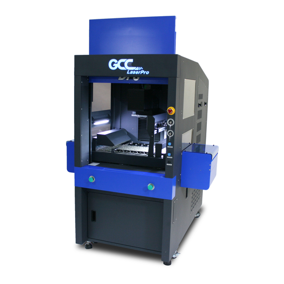
1. Introduction GCC DFS offers a total solution with auto sheet feeding system that provides labor free operation with high speed laser die cutting. Each set comes with the media tray which collects completed cutting sheets. 2. Specification Max. Speed 34M(111ft) / min Max. -
Page 5: Accessories List
3. Accessories List Power Cord x1 Back Stop x1 Auto Feeder Product Manual Interface Cable x1 Product Manual x1 www.GCCworld.com... -
Page 6: Key Components
4.Key Components Item Key Components Case Stand Conrol Panel LED Display Emergency Stop Feed Tray Feed Stopper Side Guide Suction Fan Pinch Roller Asm Blower Fan Level Sensor Separator Index 8-pin Interface Connector www.GCCworld.com... -
Page 7: Name Plate
5. Name Plate www.GCCworld.com... -
Page 8: Installation Procedure
6. Installation Procedure 6.1 Intallation of Auto Sheet Feeder for DFS a. Remove the right side PC window from the conveyor. b. Push the auto sheet feeder to insert with the DFS machine. www.GCCworld.com... - Page 9 c. Adjust the height of the DFS to make sure the level of DFS and auto feeder are the same. * NOTE: Clockwise- Machine UP / Counterclockwise- Machine DOWN Before Adjustment After Adjustment (there is a height difference) (there is no height difference) www.GCCworld.com...
- Page 10 d. Align the autofeeder with the lower panel. Upper Panel Lower Panel Lower Panel www.GCCworld.com...
- Page 11 e. Make sure the connected part between the DFS machine and the auto feeder is in the correct position. * NOTE: Please make sure the connected part is a little higher than the DFS. (auto-feeder connected part need to be right above DFS conveyor) This way is incorrect, paper will be stuck.
- Page 12 g. Connnect the Signal Cable. h. Connect the Power Cable. i. Open the top lid of Auto-Feeder and prepare to do calibation. www.GCCworld.com...
- Page 13 k. Load testing paper. m. Turn on the feeder and press “Test Run” to deliver the testing paper. n. Make sure the top edge of paper is aligned with the alignment ruler. www.GCCworld.com...
- Page 14 * NOTE: You can adjust the paper alignment by losing screw of the knob. Please kindly make sure that both horizontal and vertical orientaion need to be aligned well. o. After alignment, remove the testing paper & alignment ruler, also pull back the top lid of auto feeder.
- Page 15 f. Put the bule PC window back g. DFS Auto Sheet Feeder installation is completed. www.GCCworld.com...
-
Page 16: Intallation Of Media Collection Tray For Dfs
Intallation of Media Collection Tray for DFS Accessory Kit A. Main Panel with the screw set X1set B. Supporting Panel with the screw set X1set C. Stopper Panel X1pc D. Alignment Panel X1pc E. Connecting Panel X1pc F. Stand X2pcs a. - Page 17 b. Assemble the Main Panel (A) with the Connecting Panel (E). c. Assemble the Connecting Panel (E) with the Supporting Panel (B). www.GCCworld.com...
- Page 18 * NOTE: Please don't tighten up the screws at this stage, later we will need to fix the height by these screws with DFS machine. e. Assemble the stands of the Media Collection Tray www.GCCworld.com...
- Page 19 d. Assemble the stands on the Media Collection Tray. e. Loosen the screws from the bottom side of the DFS conveyor. www.GCCworld.com...
- Page 20 f. Connect the Media Collection Tray with the conveyor of DFS as the below picture g. Put down the stands. h. Fix the Supporting Panel (B) and tight up with the screws which are from the bottom side of the DFS conveyor. www.GCCworld.com...
- Page 21 i. Adjust the position of the Connecting Panel (E) and fix with the screws j. Place the Stopper Panel (C) as below picture k. Place the Alignment Panel (D) as below picture www.GCCworld.com...
- Page 22 m. Put back the blue PC window. n. Intallation of Media Collection Tray is completed. www.GCCworld.com...
-
Page 23: Control Paneland Function Key
7. Control Paneland Function Key Function Keys Function Clear paper path and as composition key Reset error message on the display, Tray down to reload the media Air flow volume selection SP-1 Low SP-2 SP-3 SP-4 High Run one piece of paper to keep paper length in memory for jam / burn timing control. - Page 24 Turn batch count on/off “0000” =Turn the batch count off “0100”= Set batch count amount 100 “0200”= Set batch count amount 200 “0300”= Set batch count amount 300 “0400”= Set batch count amount 400 “0500”= Set batch count amount 500 Test level sensor height Reset counter Air suction volume selection:...
-
Page 25: Loading Paper
8. Loading Paper 8.1 Fan the paper and make in order to separate the sheets 8.2 Load the Paper Note: The height of the paper stack should not exceedthe "MAX" level. 8.3 Setting the Guides www.GCCworld.com... - Page 26 NOTE: Please DO NOT adjust the paper width from the right side. Please keep the circel part at the same position. (Distance: 137mm) www.GCCworld.com...
-
Page 27: Operation Procedure
9.Operation Procedure 9.1 Level Sensor Adjustment Factory setting is scale 2 counted from bottom as shown above which is good for paper weight from 150gsm ~ 350gsm. It may need fine tuning according to paper quality variance. The elevator level should be adjusted as the following cases ●The machine has inconsistent feed. -
Page 28: Adjusting The Airflow
9.3 Adjusting the Airflow There are 4 settings for amount of air separation. Hold then press change blower volume by selecting from “SP-1” for low to “SP-4 for high. The amount of airflow should be adjusted in the following cases: ●The machine does not feed. -
Page 29: Pick-Up Pressure Roller Adjustment
9.4 Pick-Up Roller Pressure Adjustment ●Paper slip at pick up roller →Increase the pressure by turning thumbscrew clockwise. ●Paper creased by roller. →Decrease the roller pressure by turning thumbscrew counter clockwise. ●Paper skew entering into coater →Apply even pressure to both wheels by turning thumbscrews clockwise. A piece of paper can be inserted under each wheel to check for even pressures. -
Page 30: Reset Counter
9.6 Double Detection Adjustment 10.7.1 Power OFFthe Feeder 10.7.2 Open the top cover 10.7.3Lift item 3 and Insert a piece of sheetwhich is going to be fed. 9.7 Reset Counter Hold then press on to reset the counter on display. www.GCCworld.com... -
Page 31: Sensor Location
10. Sensor Location Sensor No Description Function Feed Tray Sensor Detect feed hopper has paper or not Feeding Sensor Make sure feeding is success Exit Sensor Sense paper is conveyance to DFS Machine Level Sensor Detect feed tray height Suction Fan On/Off Accurate feeding control Sure Feed Sensor Make sure paper is sucked 100% by suction head www.GCCworld.com... - Page 32 11. Trouble Shooting Guide Error Symptom and Possible Cause Action Message Press “Start” no feed E001 Load paper into the hopper 1.1 Correct skew, readjust side guide 1 Paper does not reach to S2 1.2 Check media not flat or curled E002 2 Undesired paper under S2 when 1.3 Sensor #2 dirty...
Need help?
Do you have a question about the Laser Pro DFS and is the answer not in the manual?
Questions and answers