Advertisement
Available languages
Available languages
Quick Links
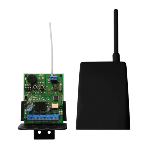
TRANSCEIVER
RX
IT
• Sistema via radio 868Mhz FM bidirezio-
nale senza fi li che trasmette il segnale di
una sicurezza al quadro di controllo.
• Il ricevitore verifi ca costantemente lo
stato dei trasmettitori connessi.
• Gestione fi no a n° 16 trasmettitori
TRANSCEIVER-TX
GB
• 868 Mhz radio bidirectional device, wire-
less which transmitt a signal to a control
device.
• The receiver check constantly the status
of the connected transmitters.
• It can manages up to 16 transmitters
TRANCEIVER-TX
FR
• Système radio 868Mhz FM bidirection-
nel sans fi l qui transmet le signal à partir
d'un dispositif de sécurité pour le dis-
positif de contrôle.
• Le récepteur surveille l'état d'émetteurs
connectés.
• Gère jusqu'à 16 émetteurs TRANS-
CEIVER-TX
DE
• 868
Mhz
bidirektionale
Funkeinheit, zur Signalübertragung.
• Der Empfänger (RX) kontrolliert ständig
den Status des verbundenen Funksend-
ers (TX)
• Er kann bis zu 16 Funksender TRAN-
CEIVER-TX regeln.
V2
TX
drahtlose
Advertisement

Related Manuals for EB TECHNOLOGY NOLOGO TRANSCEIVER-TX

Summary of Contents for EB TECHNOLOGY NOLOGO TRANSCEIVER-TX
- Page 1 TRANSCEIVER • Sistema via radio 868Mhz FM bidirezio- • Système radio 868Mhz FM bidirection- nale senza fi li che trasmette il segnale di nel sans fi l qui transmet le signal à partir una sicurezza al quadro di controllo. d’un dispositif de sécurité pour le dis- • Il ricevitore verifi ca costantemente lo positif de contrôle. stato dei trasmettitori connessi. • Le récepteur surveille l’état d’émetteurs • Gestione fi no a n° 16 trasmettitori connectés.
- Page 3 • Sistema via radio 868Mhz FM bidirezionale senza fili che trasmette il segnale di una sicurezza al quadro di controllo. • Il ricevitore verifica costantemente lo stato dei trasmettitori connessi. • Gestione fino a n° 16 trasmettitori TRANSCEIVER-TX TRANSCEIVER Istruzioni ed avvertenze TX-MINI BUZZER 1 2 3 4 JUMPER N/R PROG CHECK LED-OUT1 LED-OUT2 LED-RX1 LED-TX1 NC NA N/R1 N/R2 1 2 3 4 JUMPER J12 DIP 2 - Ingresso 1 OFF - contatto NC ON - contatto 8,2K 12 Vac/dc 24 Vac/dc DIP 3 - Ingresso 2 OFF - contatto NC ON - contatto 8,2K...
- Page 4 TRANSCEIVER Prima installazione Ricevitore Posizionare tutti i DIP in OFF sia del TX che del RX 12 V 24 V Alimentare RX 12/24 ac/dc se 12V ponticellare Jumper12V Il LED-RX1 emette un lampeggio veloce contemporaneamente ad un beep del buzzer. Reset della memoria del ricevitore Questa operazione deve essere effettuata sempre al primo utilizzo. Tenere premuto il pulsante P1 PROG del ricevitore per 12 secondi. > > Al suono del Buzzer rilasciare P1 PROG BUZZER P1 PROG Trasmettitore Ing. COSTA 1 Collegare nei morsetti del TX il contatto di sicurezza NC COM coste oppure il contatto sicurezza resistiva 8,2k Ing. COSTA 2 Selezionare con il DIP-2 per ING 1 e DIP-3 per ING 2, il tipo di ingresso: OFF seleziona l’ingresso per un contatto NC ON seleziona l’ingresso per un contatto resistivo a 8,2 K DIP 2-3 TX ON 8K2 - OFF NC...
- Page 5 TRANSCEIVER Apprendimento TX - RX Prima di effettuare la procedura di appredimento porre il dip 4 del TX come riportato: DIP 4 - TX DIP 4 - TX Apprendimento Ingresso 1 Apprendimento Ingresso 2 ING. 1 ING. 2 NC NC Apprendimento su OUT 1 (RX) Per associare una costa all’uscita OUT 1 del ricevitore procedere come segue: 1. Premere 1 volta il tasto P1-PROG del ricevitore: il LED-RX1 emette 1 lampeggio veloce. 2. Entro 60 secondi dalla pressione del tasto P1-PROG, premere il pulsante P1 del TX. 3. Se l’apprendimento è avvenuto con successo il Buzzer del ricevitore emettera un segnale acustico, se invece il TX è già presente, allora verranno emessi 3 segnali acustici. 4. Una volta effettuata la memorizzazione il ricevitore esce automaticamente dalla modalità di apprendimen- to e il LED-RX1 si spegne. Per memorizzare un altro TX sullo stesso ingresso ripartire dal punto 1. Apprendimento su OUT 2 (RX) Per associare una costa all’uscita OUT 2 del ricevitore procedere come segue: 1. Premere 2 volte il tasto P1-PROG del ricevitore: il LED-RX1 emette 2 lampeggi veloci. 2. Entro 60 secondi dalla pressione del tasto P1-PROG, premere il pulsante P1 del TX. 3. Se l’apprendimento è avvenuto con successo il Buzzer del ricevitore emettera un segnale acustico, se invece il TX è già presente, allora verranno emessi 3 segnali acustici. 4. Una volte effettuata la memorizzazione il ricevitore esce automaticamente dalla modalità di apprendimen- to e il LED-RX1 si spegne. Per memorizzare un altro TX sullo stesso ingresso ripartire dal punto 1.
-
Page 6: Esempio Di Installazione
TRANSCEIVER Configurazione a controllo attivo Configurazione a controllo passivo DIP-1 OFF sia su TX che RX DIP-1 ON sia su TX che RX Il sistema utilizzato come sicurezza per le In questa configurazione si verifica un controllo passivo detto pure: “CONTROLLO STATO IN VITA” automazioni risponde alle nomative vigenti solo se viene eseguito il test dalla centrale all’inizio di ogni della sicurezza, la ricezione del segnale da parte del... - Page 7 TRANSCEIVER Qualità del segnale con buzzer In aiuto alla buona installazione c’è il DIP-4 del RX il quale, una volta attivato e quindi posto in ON, segnala tramite il buzzer la qualità del segnale ricevuto. Il numero di beep da 1 a 5 indica la qualita’ del segnale della comunicazione, e verranno emessi ogni 12 secondi nella CONFIGURAZIONE A CONTROLLO PASSIVO, mentre ogni 120 secondi nella CONFIGURAZIONE A CONTROLLO ATTIVO. 1 beep: segnale scarso - 5 beep: segnale ottimo. Qualità del segnale con LED-RX1 Il LED-RX1 emette dei lampeggi quando si riceve la segnalazione di allarme da parte di un TX (si può fare una prova aprendo ad esempio il contatto NC del morsetto TX). Il numero di lampeggi da 1 a 5 indica la qualita’ del segnale della comunicazione. 1 lampeggio: segnale scarso - 5 lampeggio: segnale ottimo. Modo CHECK solo con DIP-1 OFF sia su TX che RX Se si preme il pulsante P2 del RX per 5 secondi il ricevitore entra in modalita’ CHECK, un segnale del buzzer confermerà l’operazione. Questa funzione permette di testare le comunicazioni con i TX. Il ricevitore RX rimane in modo CHECK per 5 minuti oppure fino a che non si preme nuovamente P2 su RX. Durante il modo...
- Page 8 • 868 Mhz radio bidirectional device, wireless which transmitt a signal to a control device. • The receiver check constantly the status of the connected transmitters. • It can manages up to 16 transmitters TRANCEIVER-TX TRANSCEIVER Instructions and warnings for installation TX-MINI BUZZER 1 2 3 4 JUMPER N/R PROG CHECK LED-L1 LED-L2 NC N/R1 N/R2 1 2 3 4 JUMPER J12 DIP 2 - IN 1 OFF - NC contact ON - 8,2K contact 12 Vac/dc 24 Vac/dc DIP 3 - IN 2 OFF - NC contact ON - 8,2K contact...
- Page 9 TRANSCEIVER First Installation Receiver Put all DIP-SWITCHES in OFF position (Tx and Rx) 12 V 24 V Give power Supply to the receiver 12/24 Ac/Dc, if 12 V make a link to JUMPER 12V. LED-0 and LED-1 fl ashes fastly and the receiver make a “ beep” sound. Cancel of the memory of the receiver This operation should be done at the fi rst installation. Cancel the memory of the receiver: keep pressed the P1 PROG > > for 12 seconds, when the receiver sounds, release the button. P1 PROG BUZZER P1 PROG Transmitter Ing. COSTA 1 Connect to the terminal board the N.C. contact or the 8.2 K resistive edge COM coste contact.
- Page 10 TRANSCEIVER Memorization of TX and RX Before starting the memorization, put dip-switch 4 of the tx as shown: DIP 4 - TX DIP 4 - TX Memorization IN 1 Memorization IN 2 IN. 1 IN. 2 NC NC How to learn a code on OUT 1 (RX) To associate one safety edge to the output OUT1 in the receiver do as follow: 1. Press once the P1 PROG of the receiver, LED TX1 fl ashes once. 2. Press P1 of the transmitter within 60 seconds after pressing P1-PROG. 3. If the buzzer beeps it means that the operation is confi rmed, if the TX is already memorized the buzzer beeps three times. 4. Once the memorization has been fi nished , the receiver goes automaticall and the LED RX1 turns off. If you need to memorize extra transmitters starts from point 1 again. How to learn a code on OUT 2 (RX) To associate one safety edge to the output OUT2 in the receiver do as follow: 1. Press twice the P1 PROG of the receiver, LED TX1 fl ashes once.
- Page 11 TRANSCEIVER Memorization when the control Check of the passive control has been activated. DIP-1 OFF DIP -1 in ON in Tx and Rx in Tx and Rx The system is used for safety to the automation There is a passive check available called “CHECK according to the laws only if the test will be done OF THE STATUS “...
- Page 12 TRANSCEIVER Signal quality of the Buzzer With DIP 4 in the receiver is in ON position, it indicates the signal quality of the buzzer. It beeps from 1 to 5 and it indicates signal quality and each 12 seconds inf the PASSIVE CONTROL MEMORIZATION, while 120 seconds each in the ACTIVE CONTROL MEMORIZATION: 1 beep not good signal, 5 beeps very good signal. LED-RX1 Signal quality The l.e.d. 1 of the receiver flashes when one Tx is on alamr (you can test when you open a N.c. contact of the terminal board of the TX). The l.e.d. flashes from 1 to 5 times and it indicates the signal quality of the transmission: 1 flash not good signal, 5 flashes very good signal Check with DIP-1 OFF in the Tx and in the RX If you push P2 of the receiver for 5 seconds, the receiver will work in CHECK : the buzzer will sound to confirm the operation. This operation can test the transmission of the TX. The receiver will be in CHECK for 5 minutes until P2 on the RX will be pressed. During the CHECK operation the receiver will sound constantly...
- Page 13 • Système radio 868Mhz FM bidirectionnel sans fil qui transmet le signal à partir d’un dispositif de sécurité pour le dispositif de contrôle • Le récepteur surveille l’état d’émetteurs connectés. • Gère jusqu’à 16 émetteurs TRANSCEIVER TX TRANSCEIVER Instructions et avertissements TX-MINI BUZZER 1 2 3 4 JUMPER N/R PROG CHECK LED-OUT1 LED-OUT2 LED-RX1 LED-TX1 NC N/R1 N/R2 1 2 3 4 JUMPER J12 DIP 2 - Entreè 1 OFF - contact NC ON - contact 8,2K 12 Vac/dc 24 Vac/dc DIP 3 - Entreè...
- Page 14 TRANSCEIVER Premiere Installation Receiver Placez tous les interrupteurs DIP en position OFF (de TX de RX) 12 V 24 V Fournir RX 12/24 ac/dc, si 12V court-circuitée avec Jumper12V La LED-RX1 clignote rapidement simultanément avec un bip du buzzer Effacer la mémoire du receiver Cette opération doit être effectuée toujours à la première utilisation. Appuyez sur pour 12 secondes P1 PROG de receiver > > Au son de Buzzer, relachez. P1 PROG BUZZER P1 PROG Trasmetteur PALPEUSE 1 Connecter aux bornes de TX le contact de la sècuritè NC COM PALP. ou le contact de la sècuritè rèsistif 8,2K PALPEUSE 2 Sélectionnez le type d’entrée, avec DIP-2 pour Entreè 1 et DIP-3 pour Entreè 2: OFF : entrée pour un contact NC ON : l’entrée pour un contact resistif 8,2 K DIP 2-3 TX ON 8K2 - OFF NC Alimentation de TX: 2 Batterie de 1,5V type LR06 AA LED-TX1 clignote rapidement puis s’éteint...
- Page 15 TRANSCEIVER Programmation TX - RX Avant la mémorisation il faut mettre DIP4 de l’émetteur comme montré: DIP 4 - TX DIP 4 - TX Programmer Entreè 1 Programmer Entreè 2 ENTREE’. 2 ENTREE’. 1 NC NC Programmer TX sur la sortie OUT 1 (RX) Pour associer la barre palpeuse à la sortie OUT1 du recepteur il faut suivre 1. Appuyer une fois P1 PROG sur le recepteur, LED RX1 clignote une fois. 2. Appuyer le touche P1 de l’émetteur entre 60 seconds qu’on a appuyè le touche P1-PROG. 3. Si le buzzer sonne une fois, ça veut dire que l’émetteur a été mémorisé correctement, si l’émetteur à été déjà mémorisé le buzzer sonne troi fois. 4. Le récepteur sort de la programmation automatiquement et LED RX1 s’éteint Pour mémoriser un autre émetteur il faut partir du point 1. Programmer TX sur la sortie OUT 2 (RX) Pour associer la barre palpeuse à la sortie OUT2 du recepteur il faut suivre: 1. Appuyez deux fois P1 PROG sur le recepteur, LED RX1 clignote une fois 2. Appuyer le touche P1 de l’émetteur entre 60 seconds qu’on a appuyè le touche P1-PROG 3. Si le buzzer sonne une fois, ça veut dire que l’émetteur a été mémorisé correctement, si l’émetteur à été...
-
Page 16: Exemple D'installation
TRANSCEIVER Configuration Active Controller Configuration avec le contrôle passif DIP-1 OFF de TX de RX DIP-1 ON de TX de RX Le système utilisé à titre de garantie pour Dans cette configuration il ya un contrôle passif l’automatisation est conforme aux réglementations également appelè: «CONTRÔLE DE L’ÉTAT DANS en vigueur que si le test est effectué par l’unité de LA VIE” sécurité, le signal reçu par le TX est activé... -
Page 17: Batterie Faible
TRANSCEIVER La qualité du signal avec buzzer Afin d’aider une installation correcte du pendage de la RX-4 de TX, lorsqu’il est activé, placé sur ON, les signaux constitués de vibreur la qualité du signal reçu. Le nombre de bips de 1 à 5 indiquent la qualité du signal de la communication, et sera publié toutes les 12 secondes dans le CONFIGURATION AVEC LE CONTRÔLE PASSIF, tandis que toutes les 120 secondes en CONFIGURATION ACTIVE CONTROL. 1 beep: signal faible - 5 beep: bon signal. La qualité du signal avec LED-RX1 LED-RX1 clignote lors de la réception du signal d’alarme d’un TX (vous pouvez faire un test en ouvrant la borne de contact normalement fermée de TX). Le nombre de bouffées de 1 à 5 indiquent la qualité ‘du signal de la communication. 1 flashing: signal faible - 5 flashing: bon signal. - Page 18 • 868 Mhz bidirektionale drahtlose Funkeinheit, zur Signalübertragung. • Der Empfänger (RX) kontrolliert ständig den Status des verbundenen Funksenders (TX) • Er kann bis zu 16 Funksender TRANSCEIVER-TX regeln. TRANSCEIVER Bedienungsanleitung TX-MINI BUZZER 1 2 3 4 JUMPER N/R PROG CHECK LED-OUT1 LED-OUT2 LED-RX1 LED-TX1 NC NA N/R1 N/R2 1 2 3 4 JUMPER J12 DIP 2 - Eingang Nr.1 OFF n.geschlossen Kontakt ON - 8.2K Kontakt 12 Vac/dc 24 Vac/dc DIP 3 - Eingang Nr.2 OFF n.geschlossen Kontakt ON - 8.2K Kontakt...
- Page 19 TRANSCEIVER Erste Installation Empfänger Alle Dippschalter in OFF-Position bringen (Tx und Rx). 12 V 24 V Stromzufuhr korrekt einstellen 12/24 AC/CD, bei 12 V einen Jumper setzen. LED-RX1 blinken schnell und der Empfänger piepst. Den speicher des FUNKSENDER LÖSCHEN Dies sollte bei der ersten Installation gemacht werden. Den Speicher des Empfängers löschen: Drücken > > Sie P1 PROG 12 Sekunden lang; wenn der Empfänger ertönt, lassen Sie den Knopf los. P1 PROG BUZZER P1 PROG Funksender SHALT. 1 Verbinden Sie den N.C. Kontakt oder den 8.2 K COM shalt Widerstandsendkontakt mit der Anschlussplatte. SHALT. 2 Wählen Sie den Eingang mit Kippschalter 2 für Eingang 1 und Kippschalter 3 für Eingang 2: OFF: Wählen Sie einen Eingang für einen N.C. Kontakt ON: Für einen 8.2 K Widerstandsendkontakt DIP 2-3 TX ON 8K2 - OFF NC...
- Page 20 TRANSCEIVER ABSPEICHERN von TX und Rx Vor der Programmierung, bringen Sie DIP 4 (TX) wie folgendes: DIP 4 - TX DIP 4 - TX Abspeichern Eingang 1 Abspeichern Eingang 2 ING. 1 ING. 2 NC NC OUT 1 (RX) Um einn Ausgant su OUT 1 zu verbiden machen Sie folgendes: 1. Drücken Sie P1-PROG 1x auf dem Empfänger (RX) LED 1 auf dem Empfänger blinkt schnell. 2. Drucken Sie P1 (TX) in 60 Sekunden (nach Sie die Taste P1-PROG gedrueckt haben) 3. Wenn das Abspechern korrekt verlaufen ist, ertönt das Funkempfänger ein Mal. Wenn der Sender schön abgespechert ist, ertönt der Summer drei Mal. 4. Wenn die Programmierung fertig ist, schaltet das Funkempfänger sofort aus und LED RX1 schaltet sich aus. Um ein neues Sender zu programieren, fangen Sie von Punkt. 1 wieder an. OUT 2 (RX) Um einn Ausgant su OUT 2 zu verbiden machen Sie folgendes: 1. Drücken Sie P1-PROG 2x auf dem Empfänger(RX) LED 1 auf dem Empfänger blinkt schnell. 2. Drucken Sie P1 (TX) in 60 Sekunden (nach Sie die Taste P1-PROG gedrueckt haben) 3. Wenn das Abspechern korrekt verlaufen ist, ertönt das Funkempfänger ein Mal. Wenn der Sender schön abgespechert ist, ertönt der Summer drei Mal. 4. Wenn die Programmierung fertig ist, schaltet das Funkempfänger sofort aus und LED RX1 schaltet sich aus. Um ein neues Sender zu programieren, fangen Sie von Punkt. 1 wieder an. -20-...
- Page 21 TRANSCEIVER Abspeichern, nachdem das Überprüfung passiven Bedienungselement aktiviert wurde. Bedieneinheit DIP-1 in ON bei Tx und DIP-1 OFF bei Tx und Rx Nur wenn die Sicherheitseinrichtungen am Es gibt eine Passivkontrolle der Betriebssicherheit Testeingang angeschlossen sind und vor jedem namens “CHECK OF THE STATUS“. Der Tx Betrieb ein automatischer Test durchgeführt wird, empfängt das Signal alle 12 Sekunden. Wenn kann das System entsprechend den gesetzlichen...
- Page 22 TRANSCEIVER Signalqualität prüfen mittels des Summers Afin d’aider une installation correcte du pendage de la RX-4 de TX, lorsqu’il est activé, placé sur ON, les signaux constitués de vibreur la qualité du signal reçu. Le nombre de bips de 1 à 5 indiquent la qualité du signal de la communication, et sera publié toutes les 12 secondes dans le CONFIGURATION AVEC LE CONTRÔLE PASSIF, tandis que toutes les 120 secondes en CONFIGURATION ACTIVE CONTROL. 1 beep: signal faible - 5 beep: bon signal. Signalqualität mittels LED-RX1 prüfen Die LED-RX1 des Empfängers blinkt, wenn eine Sicherheit am TX betätigt wird. (Das können Sie testen, indem Sie einen N.c. Kontakt der Anschlussplatte des TX unterbrechen.) Blinkt die Led 5mal hintereinander dann ist eine gute Signalübertragung vorhanden, blinkt die Led nur 1x dann ist eine schlechte Signalübertragung vorhanden.
- Page 23 TRANSCEIVER Caratteristiche tecniche / Technical features / Caractéristiques techniques / Technische Eigenschaften Dimensioni Dimensions b65 x h81 x d30 Abmessugen Alimentazione Power supply 2 battery LR06/AA 12/24 Vac/dc Alimentation (1,5V-2600mAh) Spannungsversorgung Corrente assorbita Absorbed current Courant absorbée Stromverbrauch Temperatura di esercizio Working temperature °C -20 ÷ +60 -15 ÷ +50 Température de fonctionnement Autonomia in stand-by TX - DIP1 OFF Stand-by time 1 anno, 1 year, 1 annèe, 1 Jahr Autonomie en stand by TX - DIP1 ON Autonomie im Standby...
- Page 24 EB TECHNOLOGY S.r.l. NOLOGO S.r.l. Corso Sempione 172/5, via Cesare Cantù 26, 21052 Busto Arsizio VA Italia 20020 Villa Cortese MI Italia tel. +39 0331.683310 tel. +39 0331.430457 fax.+39 0331.684423 fax.+39 0331.432496 posta@ebtechnology.it info@nologo.info www.ebtechnology.it www.nologo.info...
Need help?
Do you have a question about the NOLOGO TRANSCEIVER-TX and is the answer not in the manual?
Questions and answers