Subscribe to Our Youtube Channel
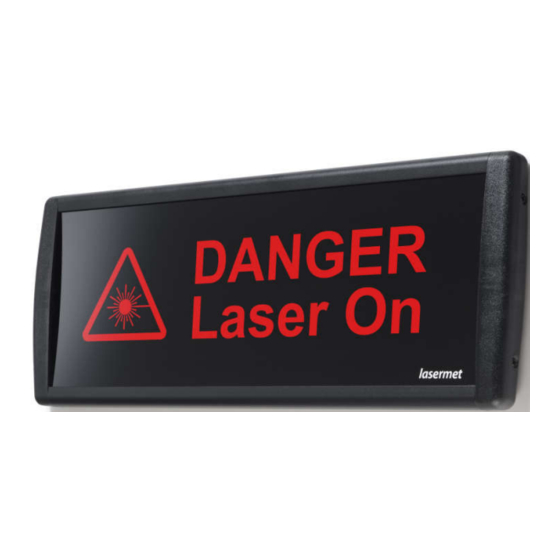
Summary of Contents for Lasermet ULTRA LEDS-ULT-470
- Page 1 LASERMET ULTRA LED SIGN INSTRUCTION MANUAL Single and Dual Aspect Illuminated Sign LEDS-ULT-470 00625-53-000 Page 1 of 11 Issue 2 16 November 2012...
-
Page 2: Table Of Contents
LEDS-ULT-470 Instruction Manual Lasermet Ultra LED Sign LEDS-ULT-470 Instruction Manual Contents Introduction ........................4 Installation ........................5 Wiring ..........................8 ‘Sign Good’ Indicators ....................10 Specifications ......................11 Contact Details ......................11 00625-53-000 Page 2 of 11 Issue 2 16 November 2012... - Page 3 LEDS-ULT-470 Instruction Manual CE Declaration of Conformity Manufacturer: Lasermet Ltd. Lasermet House, 137 Hankinson Road, Bournemouth BH9 1HR U.K. Equipment: LEDS-ULT-470 00625-00-000 Standard 00864-00-000 High Reliablity 00865-00-000 Dimmable 00866-03-000 High Reliability Dimmable Applicable Directives: Low Voltage Directive 73/23/EEC CE Directive 93/68/EEC...
-
Page 4: Introduction
The sign may be used on it’s own or in conjunction with Lasermet’s access/interlock systems. When the sign is used on it’s own, Lasermet offer a power supply and switch kit which enables easy installation and operation. Lasermet provides a full range of laser/laboratory interlock equipment including control systems, interlock switches, laser shutters, door locks, access signs, external power supplies etc. -
Page 5: Installation
If there are two or more adjacent signs stacked vertically Lasermet supply a joining strip which fills the gaps between the signs and gives a more professional appearance. - Page 6 LEDS-ULT-470 Instruction Manual Figure 1: Sign Outline Dimensions, Fixings and Cable Entry Figure 2: Mounting Arrangement using 3-way Wall Tray. 00625-53-000 Page 6 of 11 Issue 2 16 November 2012...
- Page 7 LEDS-ULT-470 Instruction Manual Figure 3: Mounting Arrangements for 4-way Wall Tray. To attach the signs to the wall tray, start with the bottommost sign, hang it on the hooks provided on the wall tray and secure using two M4 X 12 screws in the bottom two fixing holes in the sign.
-
Page 8: Wiring
With two-way signs, either one driver or the other is powered to select the illumination colour and message. Figure 8 shows a simple scheme to do this with a switch. Suitable controls are available from Lasermet. A three-way terminal block is provided on the driver board. Two terminals are used for the supply connections. - Page 9 LEDS-ULT-470 Instruction Manual EXT/NONE SENSOR +24V +24V EXT/NONE SENSOR Figure 4: Terminal Identification PSU1 +24V +24V +24V PSU2 +24V Figure 5: Connections for dual drivers using two power supplies +24V +24V +24V Figure 6: Connections for one-way dual drivers using one power supply 00625-53-000 Page 9 of 11 Issue 2 16 November 2012...
-
Page 10: Sign Good' Indicators
LEDS-ULT-470 Instruction Manual EXT/NONE SENSOR +24V +24V +24V EXT/NONE SENSOR Control 0 to +24V Figure 7: Connections when using external dimming control (Omit second driver connections if not fitted). Selector Switch +24V +24V +24V Figure 8: Two-Way Sign Control ‘Sign Good’ Indicators Each Driver board has an indicator which shows as a white spot at each end of the sign. -
Page 11: Specifications
0.65A (15.6W) at 24VDC, full brightness. Auto Dimming: Full brightness typically achieved at 1200 lux ambient. Environment: IP30 Indoor use only. All figures quoted are approximate. Lasermet reserve the right to alter specifications without prior notice. Contact Details For sales and technical support:: Lasermet Ltd.


Need help?
Do you have a question about the ULTRA LEDS-ULT-470 and is the answer not in the manual?
Questions and answers