Table of Contents
Advertisement
Quick Links
IM-895
July 2021
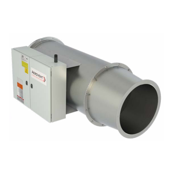
Model ADH
REVIEW AMCA BULLETIN 410 PRIOR TO INSTALLATION
This manual has been prepared to guide the users of gas door air heater units in the proper installation, operation and maintenance
procedures to ensure maximum equipment life with trouble-free operation. For safe installation, startup and operational life of
this equipment, it is important that all involved with the equipment be well-versed in proper door air heater safety practices and
read this manual. It is the user's responsibility to make sure that all requirements of good safety practices and any applicable
safety codes are strictly adhered to. Additional product and engineering information is available at www.aerovent.com.
Refer to the Safety section(s) in this manual prior to installing or servicing the door air heater. The most current version of this installation
and maintenance manual can be found on our website at www.aerovent.com/resources/im-manuals.
Table of Contents
Safety & Hazard Warnings ......................................................... 2
Receiving, Inspection & Unpacking ........................................... 3
Unit Storage ................................................................................ 3
Handling ...................................................................................... 3
General Installation .....................................................................4
Unit Installation (Gas Connections) ........................................... 5
Unit Installation (Electrical Connections) ..................................6
Control Cabinet Features .........................................................7-8
Unit Features ...............................................................................8
Centrifugal Fans
Door Air Heaters
Installation, Operation & Maintenance Manual
SAFETY NOTICE
Accessories ..................................................................................9
Check, Test & Start Procedure ............................................. 10-12
Commissioning ...........................................................................12
Sequence of Operation .............................................................13
Final Step ....................................................................................13
Maintenance ......................................................................... 14-15
Troubleshooting Guidelines ................................................. 15-16
Start-up Checklist and Report ...................................................17
Field Start-Up Sheet ..............................................................18-22
Gas
Advertisement
Table of Contents

Related Manuals for Aerovent IM-895

Summary of Contents for Aerovent IM-895
-
Page 1: Table Of Contents
It is the user’s responsibility to make sure that all requirements of good safety practices and any applicable safety codes are strictly adhered to. Additional product and engineering information is available at www.aerovent.com. SAFETY NOTICE Refer to the Safety section(s) in this manual prior to installing or servicing the door air heater. -
Page 2: Safety & Hazard Warnings
Safety & Hazard Warnings For general safety practices for air moving equipment, see AMCA Bulletin 410. Aerovent offers many safety accessories. These safety devices include (but are not limited to) Firestat, inlet and discharge screens. The use and suitability of safety devices is the responsibility of the purchaser. -
Page 3: Receiving, Inspection & Unpacking
Installation, Operation & Maintenance Manual IM-895 Receiving, Inspection & Unpacking When the equipment is received all items should be carefully checked against the bill of lading to be sure all crates and cartons have been received. Before accepting delivery, carefully inspect each carton or crate for visible shipping damage. If any damage is noticed, the carrier should make the proper notation on the delivery receipt acknowledging the damage. -
Page 4: General Installation
Installation, Operation & Maintenance Manual IM-895 General Installation The installation of this equipment shall be in accordance with the regulations of authorities having jurisdiction and all applicable codes. This equipment is to be installed by an experienced installation company and fully trained personnel. -
Page 5: Unit Installation (Gas Connections)
Installation, Operation & Maintenance Manual IM-895 Unit Installation (Gas Connections) WARNING 1. All field gas supply lines should be pressure/leak tested prior to operation. Never use an open flame. Use a soap solution or equivalent for testing. 2. Gas pressure to the unit controls must never exceed the pressure shown on the unit rating plate. The unit and its individual shutoff valve(s) must be disconnected from the gas supply during any test pressure more than 0.5 psig (3.5 kPa). -
Page 6: Unit Installation (Electrical Connections)
Installation, Operation & Maintenance Manual IM-895 Unit Installation (Electrical Connections) WARNING 1. Electric shock hazard. Could cause severe injury or death. Failure to bond the frame of this equipment to the building electrical ground by use of the grounding terminal provided or other acceptable means may result in electrical shock. Disconnect electric power before servicing equipment. -
Page 7: Control Cabinet Features
Installation, Operation & Maintenance Manual IM-895 Control Cabinet Features Feature and Factory-Mounted Option Locations Non-Fused Disconnect Switch High Temperature Limit Thermostat Control Power Transformer 8. Temperature Control Amplifier Flame Safeguard Control 9. Regulating Valve 4. Control Relay 10. Main Gas Valve Air Flow Proving Switch 11. -
Page 8: Unit Features
Installation, Operation & Maintenance Manual IM-895 Control Cabinet Features (cont.) 4. Control Relay – Includes double-pole, double throw (DPDT) contacts for sequence of operation control switching. 5. Air Flow Proving Switch – The switch monitors the pressure drop across the burner to ensure that sufficient air flow exists before allowing the burner to operate. -
Page 9: Accessories
Installation, Operation & Maintenance Manual IM-895 REMOTE PANEL Accessories (Field Installed) 1. Remote Monitoring Panel – The remote monitoring panel is used to control the operation of the door air heater. Remote monitoring panel features include: Fan Switch – All panels include a fan On/Off switch. -
Page 10: Check, Test & Start Procedure
Installation, Operation & Maintenance Manual IM-895 Check, Test & Start-Up Procedure Each unit is supplied with this Installation and Service Manual, which includes a Field Start-Up Form, starting on page 18. The Field Start-Up Form must be followed and properly filled out by the installer, with one copy kept with the unit. - Page 11 Installation, Operation & Maintenance Manual IM-895 Check, Test & Start-Up Procedure (cont.) 4. With the Fan On/Off switch still in the "Off" position, turn on the electrical supply to the unit. 5. Move the Fan On/Off switch to the "On" position (to activate the unit with heat disabled).
-
Page 12: Commissioning
Installation, Operation & Maintenance Manual IM-895 Check, Test & Start-Up Procedure (cont.) If the actual measured pressure is within (+/-) 0.50" w.c. of the calculated burner pressure above, adjust the gas valve regulator until the measured pressure matches the calculated pressure. -
Page 13: Sequence Of Operation
Installation, Operation & Maintenance Manual IM-895 Sequence of Operation – General The following describes the general sequence of operation for the unit. However, each unit may be slightly different based on unit configuration and application. Each unit includes a laminated job specific Sequence of Operation affixed to the inside of the control access door. -
Page 14: Maintenance
Installation, Operation & Maintenance Manual IM-895 Maintenance (refer to safety section) WARNING 1. Electric shock hazard. Could cause severe injury or death. Failure to bond the frame of this equipment to the building electrical ground by use of the grounding terminal provided or other acceptable means may result in electrical shock. Disconnect electric power before servicing equipment. -
Page 15: Troubleshooting Guidelines
Installation, Operation & Maintenance Manual IM-895 Maintenance (cont.) Gas Train An annual inspection of the gas control assembly should be made. Internal and external piping should be checked for leaks. Relief vents on gas controls should be checked for clogging. - Page 16 Installation, Operation & Maintenance Manual IM-895 Troubleshooting Guidelines (cont.) PROBLEM POSSIBLE CAUSE POSSIBLE REMEDY 1. See Problems "A" thru "C". 1. See Problems "A" and "C" 2. Damper end switch not functioning 2. Check and/or replace 3. Failed air flow switch 3.
-
Page 17: Start-Up Checklist And Report
Installation, Operation & Maintenance Manual IM-895 Start-up Checklist and Report Become familiar with the equipment by looking at the fan assembly drawing for special instructions and accessories. NOTICE 1. This Start-Up Check List and Report must be used in conjunction with the Installation and Service Manual originally shipped with the unit, in addition to any other accompanying component supplier literature. -
Page 18: Field Start-Up Sheet
Installation, Operation & Maintenance Manual IM-895 FIELD START-UP SHEET Customer: Sales Representative: Model Number: Serial Number: Direct Gas-Fired Equipment INITIAL INSPECTION I. Installer Responsibilities 1. Remote Panel (all interconnecting wires run from remote to unit): Temperature control interconnect wires to remote ran in:... - Page 19 Installation, Operation & Maintenance Manual IM-895 IV. Burner Inspection 1. Spark Igniter Secured Properly: 2. Flame Rod Secured Properly: 3. Ignition Wire Attached at Igniter and Transformer: 4. Unions Tight and Secure: Comments: V. Gas Manifold & Vent Piping 1. Manifold Assembly Components Tight and Securely Mounted: 2.
- Page 20 Installation, Operation & Maintenance Manual IM-895 VERIFICATION OF OPERATION NOTE: Refer to the Sequence of Operation & Wiring Diagram in the Owner’s Manual for specific data on this unit. See Factory Start-up & Test Sheet in the Unit Owner’s Manual to note the unit settings prior to shipment.
- Page 21 Installation, Operation & Maintenance Manual IM-895 III. Discharge Temperature Control Systems (Maxitrol 14 Series) 1. Modulating Regulator Valve ("MR Valve") Voltage at Low Fire: __________ Vdc Voltage at High Fire: __________ Vdc 2. Check calibration of the Discharge Air Temperature Selector. Adjust if necessary.
- Page 22 Installation, Operation & Maintenance Manual IM-895 THE ABOVE START-UP WAS PERFORMED BY: Company Name: Date: Phone Number: Fax Number: Service Tech. Name: MAKE A COPY FOR YOUR FILES AS NECESSARY The Owner Representative that I met with and discussed the unit controls and operation was:...
- Page 23 Installation, Operation & Maintenance Manual IM-895...
- Page 24 WWW.AEROVENT.COM 5959 Trenton Lane N | Minneapolis, MN 55442 | Phone: 763-551-7500 | Fax: 763-551-7501 ©2021 Aerovent...
Need help?
Do you have a question about the IM-895 and is the answer not in the manual?
Questions and answers