Table of Contents
Advertisement
Quick Links
Advertisement
Table of Contents

Related Manuals for Pall Palltronic AquaWIT IV

Summary of Contents for Pall Palltronic AquaWIT IV
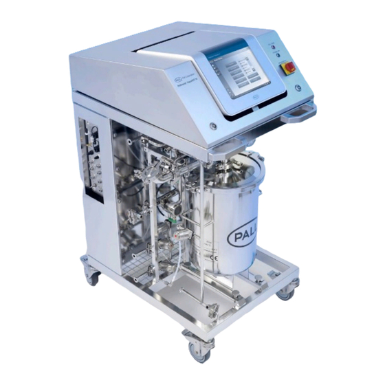
- Page 1 ® Palltronic AquaWIT IV Filter Integrity Test System Also...
-
Page 2: Table Of Contents
Operating Instructions for the Palltronic AquaWIT IV test system Page 2 Contents Safety instructions ................6 Safe Use of the Palltronic AquaWIT IV Test System ........... 6 Sources of Danger ...................... 6 Authorized Users ......................6 Filter Assembly ......................7 Personal Safety ...................... - Page 3 Operating Instructions for the Palltronic AquaWIT IV test system Page 3 5.3.6 Electronic Signature ..........................29 Configuration of the Palltronic AquaWIT System............29 5.4.1 Fill Filter settings ............................29 5.4.2 Drain Filter settings (WIT only) .........................30 5.4.3 Soak Filter settings (FF and BP only) .......................30 5.4.4...
- Page 4 Operating Instructions for the Palltronic AquaWIT IV test system Page 4 10.2 Maintenance of the Palltronic AquaWIT Base Unit ............ 58 10.2.1 Cleaning of the System ..........................58 10.2.2 Manual cleaning of the water tank ......................59 10.2.3 Sanitization ...............................60 10.2.4 Steam sanitization ............................60 10.2.5...
- Page 5 Operating Instructions for the Palltronic AquaWIT IV test system Page 5 Safety and information symbols Safety and information is identified in this instruction manual with the following symbols: Warning! identifies a dangerous situation where there is a safety risk and personal injury may follow.
-
Page 6: Safety Instructions
Before service or repair the system should be fully drained and disconnected from the electrical power supply. Warning! Only Pall trained service personnel should access the system inside the stainless steel housing lid or cabinet of the Palltronic AquaWIT system or open the integrated Palltronic Flowstar instrument! 1.3 ..Authorized Users... -
Page 7: Filter Assembly
The power supply plug must be disconnected from the power source before changing the fuse. • Repairs must only be carried out by Pall authorized service personnel. Faulty unqualified repair • work may cause accidents or injury to the user. - Page 8 Operating Instructions for the Palltronic AquaWIT IV test system Page 8 The Palltronic AquaWIT system should be shipped in the original shipping case if possible. For shipping the tank should be empty and if cleaned with chemicals as last activity the cleaning agent should be flushed out.
-
Page 9: Introduction
Operating Instructions for the Palltronic AquaWIT IV test system Page 9 2. Introduction 2.1 ..Standard Functions The instrument features the following standard functions: Forward Flow Test (FF) • Bubble Point Test (BP) • Combined Forward Flow and Bubble Point Test (FF/BP) •... -
Page 10: Set-Up Procedure
Operating Instructions for the Palltronic AquaWIT IV test system Page 10 3. Set-up Procedure 3.1 ..Connections The set up is described in the following figures and schematic drawings Figure 1: Front view : © Pall Corporation 2013 Version2.0-2... - Page 11 Operating Instructions for the Palltronic AquaWIT IV test system Page 11 Figure 2: Rear view: © Pall Corporation 2013 Version2.0-2...
- Page 12 Operating Instructions for the Palltronic AquaWIT IV test system Page 12 Figure 3: Schematic Diagram during Filter Test: The steaming and cleaning manifold is not installed during integrity testing. © Pall Corporation 2013 Version2.0-2...
- Page 13 Operating Instructions for the Palltronic AquaWIT IV test system Page 13 Figure 4: Schematic Diagram During System Steaming: The manifold for the maintenance functions is installed. © Pall Corporation 2013 Version2.0-2...
-
Page 14: Power Supply
Operating Instructions for the Palltronic AquaWIT IV test system Page 14 3.1.1 Power Supply The system is designed for input voltages of 100-240 V AC and input frequencies of 50 or 60 Hz. 3.1.2 Pressure Supply Connect the pressurized air supply to the male Stäubli* (AIR IN) connector on the left side of the instrument. -
Page 15: Air Out
Operating Instructions for the Palltronic AquaWIT IV test system Page 15 3.1.3 AIR OUT This connector allows the performance of tests without the base unit being involved in the filter tests. This connector should be used for filter tests where the filter is prepared for testing without using the AquaWIT system, for Flow Check tests and leak tests. -
Page 16: Network Connection
Operating Instructions for the Palltronic AquaWIT IV test system Page 16 1 – USB flash drive 2 – Touch screen pen Figure 6: USB flash drive, touch screen pen and the internal printer 3.1.8 Network Connection The network connection (RJ45) allows connection of the Palltronic AquaWIT system to a Ethernet network. -
Page 17: Start-Up Procedure
Operating Instructions for the Palltronic AquaWIT IV test system Page 17 4. Start-Up Procedure The system is turned on using the power switch on the right side beside the Palltronic Flowstar instrument. 4.1 ..Self Test and Warm-up Period When turned on, the screen displays the software version and then switches automatically into the Self Test mode after a few seconds. -
Page 18: Screen Navigation
Operating Instructions for the Palltronic AquaWIT IV test system Page 18 4.2 ..Screen Navigation After the Self Test has been completed the Main Menu screen is displayed. 1 = Screen Title 2 = Main Navigation 3 = Status Screen Figure 7: Main Menu and screen structure At the top of the screen, the screen title, the serial number and software version of the instrument are displayed. -
Page 19: Help Function
Operating Instructions for the Palltronic AquaWIT IV test system Page 19 4.4 ..Help Function To access the help function touch the ‘?’ button on the left side of the screen. During parameter entry the help function can be accessed using the ‘?’ button beside the parameter field. -
Page 20: Configuration Of The Palltronic Aquawit System
• To access these functions touch the TOOLS button on the left side. Level 3 access is required for these activities. The initial password is ‘Pall’ For details see Section 5.3. It is not possible to change the configuration of the system when a test is running. -
Page 21: Keyboard Beep
Operating Instructions for the Palltronic AquaWIT IV test system Page 21 If the pressure units are changed, Test results and Test programs generated prior to the change of unit will maintain the original pressure unit used for those results and programs. -
Page 22: External Pressure Transducer
Operating Instructions for the Palltronic AquaWIT IV test system Page 22 5.1.9 External Pressure Transducer Filter integrity tests are based on the differential pressure across the filter membrane. The membrane is either wetted with a wetting agent (FF + BP) or covered with water (WIT) and the flow caused by the differential pressure enables the integrity of the filter membrane to be confirmed. -
Page 23: Automation Settings
Operating Instructions for the Palltronic AquaWIT IV test system Page 23 5.1.11 Automation settings If the instrument is equipped with an active remote port (Serial, ProfiBus or DeviceNet) accessible through the BUS port at the back of the instrument this option allows the configuration of this port. -
Page 24: External Printer
Operating Instructions for the Palltronic AquaWIT IV test system Page 24 The internal printer will start printing only when the cover is open 5.2.2 External printer The external printing function enables the test record and other data to be printed on an external printer connected by USB, via the network or as a file printout. - Page 25 Operating Instructions for the Palltronic AquaWIT IV test system Page 25 If the network folder is selected the path and – if required – the user name/password for this folder can be defined Folder structure/File name The subfolder structure generated is dependent of the type of record ‘printed’. For test result printing the file name can be modified as described below.
-
Page 26: Access Management
In addition, the instrument under HLAC enables test results to be signed electronically. The settings described below can be found under Access Management on the TOOLS screen. User Level 3 required for this activity. The initial password is ‘Pall’ For details see Section 5.3. Note that passwords are case sensitive. -
Page 27: Create/Edit User
Operating Instructions for the Palltronic AquaWIT IV test system Page 27 An access level can be assigned to each individual user. The access levels are: Level 1 (Operator) Restricted to running of tests and review of test results Level 2 (Supervisor) -
Page 28: Audit Trail
Operating Instructions for the Palltronic AquaWIT IV test system Page 28 This defines the number of different passwords which must be set before a previous password can be reused. Options are: Remember the last 3, the last 5 or all passwords or OFF... -
Page 29: Electronic Signature
Operating Instructions for the Palltronic AquaWIT IV test system Page 29 The test results have no audit trail as they cannot be changed after storage except by adding an electronic signature. The audit trail can be reviewed by using the print function on the relevant screen. -
Page 30: Drain Filter Settings (Wit Only)
Operating Instructions for the Palltronic AquaWIT IV test system Page 30 5.4.2 Drain Filter settings (WIT only) The default parameters for the filter draining after the WIT can be defined here. 5.4.2.1 Drain filter pressure The pressure used to drain the filter after the Water Intrusion Test. The default value is 500 mbar. If the filter to be filled is installed above the AquaWIT system 100 mbar (1.45 psi) should be added for each... -
Page 31: Dry Filter Settings (Wit Only)
Operating Instructions for the Palltronic AquaWIT IV test system Page 31 5.4.5 Dry Filter Settings (WIT only) A drying sequence can be added after the WIT testing and the draining of the filter. This option is not designed to completely dry a filter and the drainage layer after the test. The time to completely dry a filter can be several hours. -
Page 32: Drain Tank Settings
Operating Instructions for the Palltronic AquaWIT IV test system Page 32 Port E Port B Manually (Port C) 5.4.7.2 Auto re-fill tank When enabled the tank will be refilled after each test if there is not enough water. A water supply must be cionneczed to port E. -
Page 33: Clean System Settings
Operating Instructions for the Palltronic AquaWIT IV test system Page 33 5.4.10.4 Steam valve open time Defines the time the valves are opened in the steaming sequence to allow steam to flow and condensate to be drained. The recommended time is 1 sec. -
Page 34: System Preparation
Operating Instructions for the Palltronic AquaWIT IV test system Page 34 6. System preparation Before running a test the tank should be filled with water. For the Water Intrusion test the water quality should be as follows: Fill the water tank with approximately 20 liters of water DI-water conductivity: 1-20 µS/cm... -
Page 35: System Operation
Operating Instructions for the Palltronic AquaWIT IV test system Page 35 7. System Operation 7.1 ..Test Set-Up for Testing Hydrophobic Filter Before a Water Intrusion test is started the Palltronic AquaWIT system must be connected to the filter system. Use the white PTFE pneumatic hose and the stainless steel quick connections (type Stäubli) and clamp/quick connection adapter supplied or other proper adaptors to fit the filter system. - Page 36 Operating Instructions for the Palltronic AquaWIT IV test system Page 36 The connections should be made according to the following diagram: Figure 9: External valve connections (WIT) Valve V 10 (Filter Housing Drain) is normally closed. The valve is open during filling and draining and closed during the test and drying of the filter.
-
Page 37: The Water Intrusion Test (Wit)
Operating Instructions for the Palltronic AquaWIT IV test system Page 37 7.2 ..The Water Intrusion Test (WIT) 7.2.1 Introduction The Water Intrusion Test is designed to test the integrity of hydrophobic membrane filters. The test is based on measuring the water flow across a hydrophobic membrane completely covered with water at a defined test pressure on the upstream side. - Page 38 Operating Instructions for the Palltronic AquaWIT IV test system Page 38 used for filling the filter and port F is used to drain the filter after the test. When using an external water source the pressure of the water supply should be reduced to 2000 mbar (29 psi) and the temperature should be in the required range 18-25 °...
-
Page 39: Procedure Of The Water Intrusion Test
Operating Instructions for the Palltronic AquaWIT IV test system Page 39 Dry filter time This defines the total time of the drying sequence. The Palltronic AquaWIT system is not capable to completely dry a filter. For this warm air and vacuum will be required to dry a filter within a reasonable time. - Page 40 Operating Instructions for the Palltronic AquaWIT IV test system Page 40 Filter filling After entering the test parameters and pressing the [OK] button the test starts and the Palltronic AquaWIT system checks first the setup before pressurizing the tank. Then the system waits until the level sensor L1/L2 indicates that the filter assembly is filled.
-
Page 41: Test Set-Up For Testing Hydrophilic Filter
Operating Instructions for the Palltronic AquaWIT IV test system Page 41 7.3 ..Test Set-Up for testing hydrophilic filter Before a Forward Flow or Bubble Point test including filter wetting is started the Palltronic AquaWIT system must be connected to the filter system. Use the white pneumatic hose and the stainless steel quick connections (type Stäubli) and clamp/quick connection adapter supplied or other proper adaptors to... -
Page 42: Connection Of External Valves
Operating Instructions for the Palltronic AquaWIT IV test system Page 42 7.3.1 Connection of External Valves The Palltronic AquaWIT test system can control three compressed air actuated external valves installed on the upstream side of the filter and a valve (V15) on the downstream side. For this purpose there are Stäubli connections with the labels V10, V11, V12 and V15 located on the back of the instrument. -
Page 43: The Forward Flow Test (Ff)
Operating Instructions for the Palltronic AquaWIT IV test system Page 43 7.4 ..The Forward Flow Test (FF) 7.4.1 Introduction The Forward Flow Test is designed to test the integrity of hydrophilic and hydrophobic membrane filters. The test is based on measuring the gas flow across a completely wetted membrane at a defined test pressure on the upstream side. - Page 44 Operating Instructions for the Palltronic AquaWIT IV test system Page 44 is used for filling the filter and port F is used to drain the filter after the test. When using an external water source the pressure of the water supply should be reduced to 2000 mbar (29 psi) and the temperature should be in the required range.
-
Page 45: Procedure Of The Forward Flow Test
Operating Instructions for the Palltronic AquaWIT IV test system Page 45 The test can be observed in the list displayed in the Test Results screen and started by touching the ‘Start’ button. 7.4.3 Procedure of the Forward Flow Test Manual Abort The following automatic procedure can be aborted at any time by touching the ‘Abort’... -
Page 46: The Bubble Point Test
Operating Instructions for the Palltronic AquaWIT IV test system Page 46 7.5 ..The Bubble Point Test 7.5.1 Introduction The Bubble Point Test is designed to detect the largest pores of hydrophilic and hydrophobic membrane filters. The test is based on measuring the gas flow across a completely wetted membrane at increasing pressure on the upstream side. - Page 47 Operating Instructions for the Palltronic AquaWIT IV test system Page 47 When using an external water source the pressure of the water supply should be reduced to 2000 mbar (29 psi) and the temperature should be in the required range.
- Page 48 Operating Instructions for the Palltronic AquaWIT IV test system Page 48 Touch the ‘Start’ button to start the Forward Flow Test. If a test is already running when pressing the ‘Start’ button, the new test will be automatically put in a queue.
-
Page 49: The Combined Forward Flow And Bubble Point Test
Operating Instructions for the Palltronic AquaWIT IV test system Page 49 7.6 ..The Combined Forward Flow and Bubble Point Test The combined Forward Flow and Bubble Point test (FF+BP) performs a standard FF Test followed by a BP Test without the initial leak test. -
Page 50: Test Programs
8.1 ..Creating Test Programs To create a new test program, touch ‘Test Programs’ from the Main Menu screen. Level 2 Access is required for this activity. The initial password is ‘Pall’. For details see Section 5.3 Select the type of test:- Forward Flow (FF), Bubble Point (BP), Combined Forward Flow and Bubble Point (FF/BP), Water Intrusion (WIT) , Leak Test (LT) or Pressure Decay Test (PD) - for the test program. -
Page 51: Printing Test Programs
Operating Instructions for the Palltronic AquaWIT IV test system Page 51 Select the test program from the list. The single arrow key will refresh the screen to show the next ten test programs and the double arrow will move the selection up or down 25 test programs. Touch the ‘Deac tivate’... -
Page 52: Recall Of Stored Test Results
Operating Instructions for the Palltronic AquaWIT IV test system Page 52 9. Recall of Stored Test Results The instrument automatically stores all generated test results. To redisplay or reprint a test result that has been saved touch the ‘Test Results’ button in the Main Menu screen. -
Page 53: Maintenance Of The Palltronic Aquawit System
Pall approved service engineers. We recommend that the equipment undergoes a full service every year by Pall, during which all components are cleaned and checked and a recalibration is carried out. A calibration is recommended at least every 12 months. This can be performed locally on site or at an approved Pall service center. -
Page 54: Printer Test
± 5 % of the certified flow value. In the event of results outside this limit the test should be repeated. If further results outside this limit are obtained, contact your local Pall office or Pall distributor. -
Page 55: Changing The Printer Paper
Ensure all parts of the valve are completely dry and then reassemble. • If the external vent valve requires further servicing or repair contact your local Pall sales office or • distributor. -
Page 56: Cleaning The Instrument
Operating Instructions for the Palltronic AquaWIT IV test system Page 56 1. Once this cleaning has been completed twice on an external vent valve, discard the valve and re- order a complete valve assembly using Pall part number S26.5.12. 1 = Male Stäubli Connector... - Page 57 Operating Instructions for the Palltronic AquaWIT IV test system Page 57 Warning! Take care that the lid is fully open and secured. (see figure 13) Figure 13: Securing the top lid Disconnect the power supply and the other connections on the rear of the instrument. Disconnect the pressure connections and the connection for the external vent valve and the external pressure transducer on the left side of the instrument.
-
Page 58: Maintenance Of The Palltronic Aquawit Base Unit
Operating Instructions for the Palltronic AquaWIT IV test system Page 58 10.2 Maintenance of the Palltronic AquaWIT Base Unit Warning! The maintenance functions should only be performed by appropriate trained operators For all maintenance functions the manifold including valve V14 must be installed (see figure 14) The system checks the installation of V14 and will not start the sequence if the manifold is not detected. -
Page 59: Manual Cleaning Of The Water Tank
Operating Instructions for the Palltronic AquaWIT IV test system Page 59 Warning! If hot cleaning agents are used the touching of the stainless steel parts, especially the pipe work of the Palltronic AquaWIT system during cleaning may cause burns. Use thermal safety gloves during the cleaning procedure. -
Page 60: Sanitization
Operating Instructions for the Palltronic AquaWIT IV test system Page 60 10.2.3 Sanitization The Palltronic AquaWIT system can be sanitized by steam or by hot water. Warning! Touching the stainless steel parts, especially the pipe work of the Palltronic AquaWIT system during steaming or hot water sanitization may cause burns. Use thermal safety gloves during the sanitization procedure. -
Page 61: Hot Water Sanitization
Operating Instructions for the Palltronic AquaWIT IV test system Page 61 The timer starts when the target temperature is reached and/or exceeded. If the defined steaming time is completed the system will be vented slowly until the temperature in the tank drops to 100 °C. -
Page 62: Dismantling Of The Tank
Operating Instructions for the Palltronic AquaWIT IV test system Page 62 Define the Pressure source. It can be either the Flowstar or a separate pressure supply connected to port <B>. A separate pressure supply will be more efficient due to the flow restriction by the Palltronic Flowstar. - Page 63 Operating Instructions for the Palltronic AquaWIT IV test system Page 63 Figure 15: Dismantling the tank - Connection A and B Disassemble the temperature and the level sensors. (see figure 16) The level sensors should be removed slowly and by turning them slightly when pulling them out.
- Page 64 Operating Instructions for the Palltronic AquaWIT IV test system Page 64 As next step open the connection C and D (see Figure 17) Figure 17: Dismantling the tank – Connection C and D Finally open the screws at the bottom of the tank. The screws in front must be fully removed, the screws at the back must only be opened.
-
Page 65: Additional Functions
Operating Instructions for the Palltronic AquaWIT IV test system Page 65 11. Additional functions 11.1 Fill tank After connecting the water supply to the defined port the tank can be filled with water until either the upper level sensor in the tank or the timeout is reached, Avoid filling the tank with high pressure (>... -
Page 66: Drain Filter
Operating Instructions for the Palltronic AquaWIT IV test system Page 66 The optimum filling pressure can be calculated in the following way: (Height of the filter housing over the Palltronic AquaWIT system in meters x 500 + 500) mbar or (Height of the filter housing over the Palltronic AquaWIT system in inches x 0.2 + 7.2) psig. -
Page 67: Palltronic Aquawit Mux Extension
Operating Instructions for the Palltronic AquaWIT IV test system Page 67 12. Palltronic AquaWIT MUX extension The optional Palltronic AquaWIT MUX extension allows the testing of four filters in series controlled by the Palltronic AquaWIT system. After installing the filters and programming the test parameters for these four filter the tests will be performed four all channels including filter preparation without any further activity by the operator required. -
Page 68: Enabling The Mux Control On The Palltronic Aquawit System
Operating Instructions for the Palltronic AquaWIT IV test system Page 68 12.1.3 Enabling the MUX control on the Palltronic AquaWIT system To enable the channel selection the MUX function must be activated in the configuration of the Palltronic AquaWIT. For this the system configuration must be opened from the Tools menu and at ‘Enable AquaWIT’... -
Page 69: Data Transfer
//IP address of the network host/name of the shared folder/… //Domain name of the network host/name of the shared folder/… If further details are needed data export over a network, please contact your Pall representative If the network folder requires a user name and password this can be defined and stored for future use as option. -
Page 70: Export Test Results
Operating Instructions for the Palltronic AquaWIT IV test system Page 70 [Test type code][YYYYMMDD][ID1][ID2][N] The Self Test and Flow Check tests will be stored as [Test type][YYYYMMDD][N] Test Programs • Test programs will be printed as PDF files into a folder named Test programs. -
Page 71: Export Configuration
Operating Instructions for the Palltronic AquaWIT IV test system Page 71 The test results wil be stored in a folder which name includes the serial number of the instrument and the subfolder ‘Test results’ The file name is created by the instrument and includes the test type followed by the date when the test was performed in the format YYYYMMDD. -
Page 72: Export Access Management Configuration
Operating Instructions for the Palltronic AquaWIT IV test system Page 72 When importing data to the instrument all the current existing data of this type will be overwritten! The new configuration will be active after a restart. The configuration audit trail will be the initial version generated by the system with the time stamp of the transfer. -
Page 73: Import Test Programs
Operating Instructions for the Palltronic AquaWIT IV test system Page 73 The data will be stored in a folder. The folder name will be the serial number of the instrument and a subfolder with the type of data and the transfer date. -
Page 74: Deletion Of Records
It is possible to erase records from the instrument. User Level 3 required for this activity. The initial password is ‘Pall’. For details see Section 5.3. For the deletion of records go to <Tools> followed by <Backup> and touch <Backup>. -
Page 75: Remote Control And Data Logging
It also enables test results to be logged. The FieldBus option is only activated when the type of Bus is specified when ordered. Otherwise this function must be activated by the Palltronic service team. Contact your local Pall representative for details. -
Page 76: Error Messages
Operating Instructions for the Palltronic AquaWIT IV test system Page 76 15. Error Messages The table below enumerates most common error messages and their possible causes. The error messages are displayed on the screen and can be printed out. If errors are encountered that are not described here, please contact Pall. - Page 77 Operating Instructions for the Palltronic AquaWIT IV test system Page 77 FLOW TOO HIGH Flow >1000 ml/min (FF test) or >50 Replace filter if needed. • ml/min (WIT) Check system for leaks. Re-wet (FF-Test) and re-test Leak in the filter system the filter •...
- Page 78 Operating Instructions for the Palltronic AquaWIT IV test system Page 78 LEAKTEST FAILURE Major leak in the filter system under Check system for leaks. • test Re-wet and re-test filter. Replace filter if needed. Filter not wetted completely • Filter has a major defect •...
- Page 79 Operating Instructions for the Palltronic AquaWIT IV test system Page 79 EXT: VALVE ERROR External Valve not connected Check external valve • External Valve not opening • AquaWIT Error Message Possible Causes Action BASE NOT CONNECTED Flowstar could not detect base unit...
-
Page 80: System Retirement
There is the option to send the Palltronic AquaWIT system back to Pall after retirement. Otherwise the Palltronic Flowstar Instrument. The control box and the sensors should be removed and disposed as electrical/electronical waste. -
Page 81: Technical Data
Operating Instructions for the Palltronic AquaWIT IV test system Page 81 17. Technical Data Physical Dimensions Size: 1189x575x856 mm (HeightxWidthxDepth) Weight: approx 100 kg (With tank empty) Tank volume: 18 l (up to level switch L3 in the tank) Filter Tests... - Page 82 Operating Instructions for the Palltronic AquaWIT IV test system Page 82 Measuring Range Forward Flow Test: 0.1 – 1000 ml/min Water Intrusion Test: 0.02 - 50 ml/min water Bubble Point Test: 400 - 6500 mbar (0.725 – 94.2 psi) Accuracy Forward Flow Test: ±...
- Page 83 To meet the full requirements of IP 54 splash proof electrical connections to the instrument are necessary. These are available as accessories; please contact your local Pall representatives for details. Operating Temperature: +5° C to +50° C (+41° F to +122° F) Storage Temperature: -20°C to +70°...
- Page 84 Operating Instructions for the Palltronic AquaWIT IV test system Page 84 © Pall Corporation 2013 Version2.0-2...
- Page 85 2200 Northern Boulevard 25 Harbour Park Drive East Hills, New York 11548-1289 Port Washington, New York, 11050 Pall Corporation has offices and plants throughout the world in locations including: 800.717.7255 toll free Argentina, Australia, Austria, Belgium, Brazil, Canada, China, France, Germany, India, 516.484.5400...
Need help?
Do you have a question about the Palltronic AquaWIT IV and is the answer not in the manual?
Questions and answers