Table of Contents
Advertisement
Quick Links
USER'S MANUAL
MODEL 781 SIGNAL CONDITIONING UNIT
Serial No.________________
850 Perimeter Road
Manchester, NH 03103 USA
Tel (603) 669-6400
Fax (603) 622-2690
sales@jewellinstruments.com
www.jewellinstruments.com
Copyright ©2013 by Jewell Instruments LLC. All rights reserved.
Document No. B-88-1006, Rev. B
Advertisement
Table of Contents

Subscribe to Our Youtube Channel
Related Manuals for JEWELL 781


Summary of Contents for JEWELL 781
- Page 1 USER’S MANUAL MODEL 781 SIGNAL CONDITIONING UNIT Serial No.________________ 850 Perimeter Road Manchester, NH 03103 USA Tel (603) 669-6400 Fax (603) 622-2690 sales@jewellinstruments.com www.jewellinstruments.com Copyright ©2013 by Jewell Instruments LLC. All rights reserved. Document No. B-88-1006, Rev. B...
-
Page 2: Table Of Contents
USER’S MANUAL MODEL 781 SIGNAL CONDITIONING UNIT TABLE OF CONTENTS 1.0 General Information ..................... 2 1.1 Introduction ......................2 1.2 General Specifications ..................2 2.0 Operation ......................6 2.1 Using the Controls; Meaning of the Indicators ............6 3.0 Maintenance and Troubleshooting 3.1 Routine Maintenance ..................... -
Page 3: General Information
1.0 GENERAL INFORMATION 1.1 Introduction: The model 781 Signal Conditioning Unit (SCU) is a compact module that may be used with all Jewell Instrument tilt sensors. Internal SCU electronics provide simultaneous excitation of two electrolytic tilt transducers, and condition the returned signals into two analog DC voltages. The SCU provides both single-ended and differential outputs on each of its two tilt channels. - Page 4 EXTERNAL CONNECTIONS Dual screw-terminal barrier strips TEMPERATURE RANGE -20°C to +70°C [-4°F to +158°F] Operational -30°C to +100°C [-22°F to +212°F] Storage HUMIDITY RANGE 0 to 100%, noncondensing & nonsubmersible SIZE 3.5" x 5" x 8.4" (8.8 cm x 12.7 cm x 21.3 cm) WEIGHT 2 lbs.
- Page 5 B-88-1006, REV. B...
- Page 6 B-88-1006, REV. B...
-
Page 7: Operation
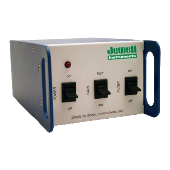
2.0 OPERATION 2.1 Using the Controls; Meaning of the Indicators: There are three 2-position control switches on the front panel of the SCU (Figure 1). The first is the ON-OFF power switch, the second is the HIGH-LOW gain switch, and the third is the ON-OFF low-pass filter switch. -
Page 8: Maintenance And Troubleshooting
NOTE: WATER DAMAGE TO INTERNAL COMPONENTS VOIDS THE WARRANTY! Apart from the procedures described below, the SCU is not field-serviceable. Therefore, if you should encounter problems not described herein, please contact a Jewell Instruments sales representative at (603) 669-6400 for assistance. -
Page 9: Determining The Cause Of Malfunctions
THE PCB will cause PERMANENT TILT SENSOR DAMAGE that is not cover by the warranty. If an inspection of the connections to the printed circuit board does not correct the problem, please call a Jewell Instruments sales representative at (603) 669-6400 for assistance. CAUTION NEVER USE AN OHMMETER TO MEASURE JEWELL INSTRUMENTS TILT SENSORS. -
Page 10: Warranty And Assistance
Jewell Instruments. No other warranty is expressed or implied. The warranty is void if the equipment is subjected to lighting strikes, or other large potential gradients, or if it is otherwise abused. -
Page 11: Custom Specification For Your Equipment
However, it will operate any Jewell Instruments tilt transducer. If you purchase new tilt transducers for use with the SCU, they should be calibrated with the SCU prior to use. Jewell Instruments will perform these calibrations if the Signal Conditioning Unit is shipped prepaid to our factory at the time the order for new transducers is place. - Page 12 Scale Factors are determined by moving the transducers through a range of angles and recording the SCU output at each angle. Linear regression analysis then determines the slope of the straight line that best fits the data. This slope is the Scale Factor. Reported below are Scale Factors and their corresponding maximum nonlinearity.
-
Page 13: Revision Table
APPENDIX C - Revision Table REV. PAGE NOS. ECN NO. DESCRIPTION OF CHANGE DATE "Jewell" was "Applied Geomechanics" 25087 2/13/13 Added Appendix C for revision record B-88-1006, REV. B...
Need help?
Do you have a question about the 781 and is the answer not in the manual?
Questions and answers