Table of Contents
Advertisement
Advertisement
Table of Contents

Related Manuals for Plum eSTER x40


Summary of Contents for Plum eSTER x40
- Page 1 WIRELESS ROOM THERMOSTAT eSTER_x40 FOR HEATING CIRCUIT CONTROLLERS ONLY COOPERATES WITH THE ecoMAX SERIES OF THE BOILER CONTROLLERS ISM_xSMART* * The ISM_xSMART radio module is standard equipment for the thermostat. INSTALLATION AND OPERATING MANUAL ISSUE: 1.0 04-2019...
-
Page 3: Table Of Contents
CONTENTS RECOMMENDATIONS REGARDING SAFETY ..4 GENERAL INFORMATION ........4 INFORMATION ABOUT DOCUMENTATION ..4 STORAGE OF DOCUMENTATION ......4 APPLIED SYMBOLS ..........4 DECLARATION OF CONFORMITY ......4 DIRECTIVE WEEE 2012/19/UE ......5 THE FIRST START OF THE THERMOSTAT ..... 5 THERMOSTAT MAIN SCREEN ...... -
Page 4: Recommendations Regarding Safety
The full text of the Declaration of Conformity is available at www.plum.pl in the Downloads section of the appliance website. -
Page 5: Directive Weee 2012/19/Ue
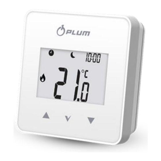
7. Directive WEEE 2012/19/UE 9. Thermostat main screen Purchased product is designed and made of materials of highest quality. The product meets the requirements of the Directive 2012/19/EU of 4 July 2012 on waste electrical electronic equipment (WEEE), according to which it is marked symbol crossed-out... -
Page 6: Thermostat Settings
main controller preset The first press causes to edit the current temperature in the room is not reached; preset temperature, but does not change the 10. value of room temperature and edition of value. Only another press changes the value. the preset room temperature;... - Page 7 of 5 seconds. Editable operating modes that • - the mode enables a single charging are related to parameter settings in the user of the HUW container for the set time menu (point 11): (P14), which appears for editing: • Schedule –...
-
Page 8: Edition Of The Schedules
00.30). The second interval is 00:30 (which means the interval 00.30-01: 00). Use buttons to move between intervals (48 intervals, every 0.5 h). For each interval, the preset temperature "Night" or "Day" can be set. The button assigns the night or day temperature for a given interval. -
Page 9: User Menu
mark copied (pattern) The parameters are selected using the buttons and the button is confirmed by the selection. Description „Sch” Schedules, point 9.3 „CPy” Copying schedules, point 9.4 selection of days to fill with the „PAr” Paring, point 15.2 Setting the clock pattern „Day”... -
Page 10: Service Menu
level indicator. Turning on (on) or off (oFF) the weather temperature indication. Turning on (on) or off (oFF) display on the clock screen. Holding the button for 2 seconds will exit the user menu to the main screen. 11.1 Service menu The entry to the service menu is done by holding simultaneously... -
Page 11: Installation Of The Thermostat
The entry to the main regulator parameters the thermostat should be within the range of 5..35C, menu is made by pressing the button for • the chosen location should ensure free air 2 seconds. Individual menu parameters are circulation and should be located away visible as consecutive markings displayed on from heat-emitting sources, eg electronic the screen in no. -
Page 12: Inserting Or Replacing The Batteries In The Thermostat
Screw holes Assembly screw In order to place the thermostat on a flat surface, use a dedicated stand. It is recommended to use alkaline batteries to power the thermostat. thermostat's working time depends quality batteries used. 15. Radio module 15.1 Installation and connection of the radio module to the main controller... -
Page 13: Max. Length 30 M
Screw holes Assembly screw Terminals D +, D-, GND, 12 VDC of the radio module should be connected to the RS485 transmission socket of the main controller, in accordance with point. 15.5 When connecting the transmission and power supply attention should 4x0.5 mm wire, be paid to the proper polarity of... -
Page 14: Resetting The Memory Of The Radio Module
pairing mode by briefly pressing the P button or wait until the active pairing time expires. If the thermostat has never been After establishing the radio connection with paired with radio module (factory setting), then pairing thermostat main controller Information menu, the thermostat will be occurs after pressing... -
Page 15: Controllers
software of the main controller so that this - flashing, there is no radio connection or cooperation will be ensured. there is a weak signal and you should choose a different place to install the thermostat. The radio module can operate with The value of the radio signal strength can be up to three thermostats. - Page 16 Connection of the module to the ecoMAX910R1, ecoMAX920P1: 1 - radio module, 2 – main controller. It is not recommended to turn off power supply main regulator due to frequent attempts to obtain a radio connection of the thermostat with a radio module, which leads to a quick discharge of the battery in the thermostat.
-
Page 17: Technical Data
18. Description of possible faults 16. Technical data Symptoms Tips eSTER_x40 2 x AA (LR6) 1,5V - The thermostat Check the correct installation thermostat power alkaline batteries is not working. of the battery - point 14.1 or supply display whether the batteries used are 5..12 directly ISM_xSMART... - Page 20 Wspólna 19, Ignatki 16-001 Kleosin Poland plum@plum.pl www.plum.pl...
Need help?
Do you have a question about the eSTER x40 and is the answer not in the manual?
Questions and answers