Table of Contents
Advertisement
Quick Links
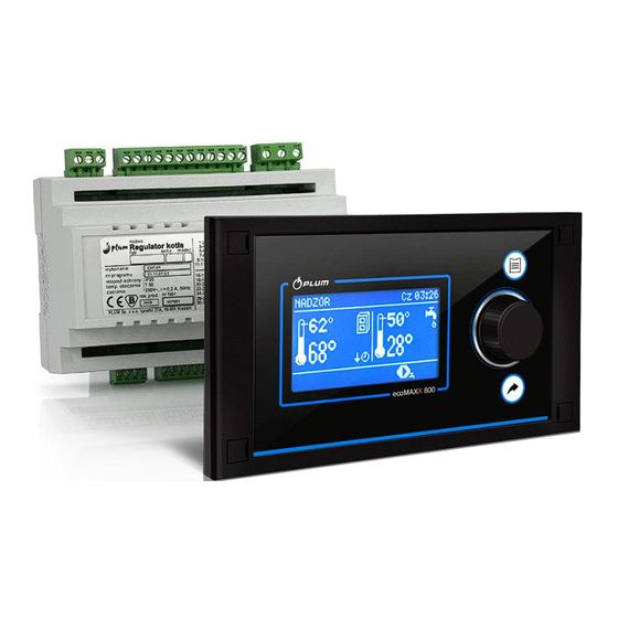
Boiler regulator
ecoMAXX 800, model R2
FOR SOLID FUEL BOILERS
A, B, C – functions chich are available in module, respectively: A, B, C
* room panel ecoSTER200 (module B, C and ecoSTER200 are not part of standard equipment)
SERVICE AND ASSEMBLY MANUAL
ISSUE: 1.3
SOFTWAREE:
MODULE
v.01.XX.XX
2013-09-13
PANEL
v.01.XX.XX
Advertisement
Table of Contents

Related Manuals for Plum ecomaxx 800 R2


Summary of Contents for Plum ecomaxx 800 R2
- Page 1 Boiler regulator ecoMAXX 800, model R2 FOR SOLID FUEL BOILERS A, B, C – functions chich are available in module, respectively: A, B, C * room panel ecoSTER200 (module B, C and ecoSTER200 are not part of standard equipment) SERVICE AND ASSEMBLY MANUAL ISSUE: 1.3 MODULE PANEL...
- Page 3 PRINCIPLES FOR USAGE OF Individual Fuzzy Logic CONTROLLED BOILER: The regulator must be programmed individually for the given type of boiler and fuel, p. 21.1! It is inadmissible to change the type of gear-motor, fan, and to make other changes in the boiler fittings which can influence the burning process.
-
Page 4: Table Of Contents
TABLE OF CONTENTS 11.5 IP ..........24 PROTECTION RATE 1 RECOMMENDATIONS REGARDING SAFETY....5 11.6 E .......... 24 LECTRIC CONNECTION 2 GENERAL INFORMATION .......... 6 11.7 T ...... 27 EMPERATURE SENSORS CONNECTION 11.8 W ......28 EATHER SENSORS CONNECTION 3 INFORMATION ABOUT DOCUMENTATION ....6 11.9 T ...... -
Page 5: Recommendations Regarding Safety
RECOMMENDATIONS REGARDING regulator SAFETY intrinsically safe device, which means that in the case of Requirements concerning safety malfunction it can be the source described detail of a spark or high temperature, which presence individual chapters this flammable dusts or liquids can manual. -
Page 6: General Information
The regulator manual is divided into two General information parts: for user and fitter. Yet, both parts Boiler regulator ecoMAX 800 model P1, contain important information, significant for version L, is a modern electronic device safety issues, hence the user should read intended to control pellet boiler operation. -
Page 7: Regulator Instruction Manual
REGULATOR INSTRUCTION MANUAL ecoMAXX 800R2... -
Page 8: Operating The Regulator
- symbol of decreasing preset boiler temperature from opening room Operating the regulator thermostat contacts; Buttons description - Preset boiler temperature decrease due to thermostat disconnection (room temperature is reached); - Preset boiler temperature decrease due to activated time spans; –... -
Page 9: Regulator Start-Up
Details can be found in section 7.21. Note: the fuel level can be viewed also on room panel ecoSTER200. Fig. 5 Manual feeder start-up The feeder starts once the knob has been pressed on a feeder symbol. Feed such amount of fuel so that it appears at the end of retort. -
Page 10: Operation - Standard Mode
If the user does not switch-over the regulator to OPERATION mode, the regulator will heat-up the boiler to preset temperature + 10 C, and will automatically enter OPERATION mode, subsequently SUPERVISION because the preset boiler temperature been reached. Fig. 8 Cycles of Blow-In and Feeder operation in OPERATION mode;... -
Page 11: Operation-Fuzzy Logic Mode
OPERATION–Fuzzy Logic mode Switching off output modulation in Fuzzy Logic Upon change of boiler regulation mode from In case the regulator works in SUMMER Standard to Fuzzy Logic, regulator works in mode of operation or with a little heat OPERATION mode and modulates the boiler demand (in Spring and Autumn), modulation output to achieve constant preset boiler of boiler output is not justified. -
Page 12: Selection Of Fuel
SUPERVISION mode, regulator Examples of SUPERVISION mode settings supervises that the fire in the furnace (fuel: hard coal): not damped. For this purpose, the fan and - Feeder Interval - Superv. = 15-30min. the feeder work intermittently and operate - Feeding Time-Superv. = 12s, for a certain time, less frequently than in - Blow-in operation extending- Superv. -
Page 13: Disinfection Of Huw Container
7.14 Disinfection of HUW container 5°C. To reach room temperature 18°C value of heating curve paralel movement must be The regulator has a function of automatic, set for -2°C. periodic heating of HUW container to 70 °C to eliminate bacterial flora from the HUW In this configuration a thermostat can be container. -
Page 14: Weather Control
Example. Preset temperature in heating room (set in ecoSTER200) = 22 degrees C. Measured temperature in room (using ecoSTER200) = 20 degrees C. room temperature factor = 15 Preset mixer temperature will be increased by (22 degrees C – 20 degrees C) x 15/10 = 3 degrees C. -
Page 15: Control Of Huw Circulating Pump
This feature enables automatic reduction of 7.20 Manual control preset temperature, which improves heat Regulator offers possibility to manual start of comfort and reduces fuel consumption. It is working equipment such like pump, feeder motor or fan. This feature enables checking indicated with a sign whether the equipment is fault-free and properly connected. - Page 16 Fuel level indicator service Calibration Each time when fuel silo is filled to required If the service parameters of the boiler: level it is necessary to press and keep the Feeder Efficiency and Tank Capacity knob in main window. Following info will properly set, calibration is not necessary - appear: regulator should properly calculate fuel level.
-
Page 17: User Manual Of Controller Installation And Service Settings
USER MANUAL OF CONTROLLER INSTALLATION AND SERVICE SETTINGS ecoMAXX 800, model R2... -
Page 18: Hydraulic Diagrams
Hydraulic diagrams Diagram 1 Fig. 14 Diagram with 4-way control valve for central heating circuit , where: 1 – boiler, 2 – ecoMAXX regulator – module A, 3 – ecoMAXX regulator – control panel, 4 – fan, 5 – feeder temperature sensor, 6 - gear-motor, 7 –... -
Page 19: Diagram 2
Menu Service Settings Circulating Output H Pump Circulation support Pump Service Settings Diagram 2 where Fig. 15 Diagram with 3-way thermostatic valve to secure return water temperature : 1 – boiler, 2 – ecoMAXX regulator – module A, 3 – ecoMAXX regulator – control panel, 4 – fan, 5 – feeder temperature sensor, 6 - gear-motor, 7 –... -
Page 20: Diagram 3
Diagram 3 Fig. 16 Diagram with two additional mixer circuits upon connection of additional Module B where : 1 – boiler, 2 – ecoMAXX regulator – module A, 3 – ecoMAXX regulator – control panel, 4 – fan, 5 – feeder temperature sensor, 6 - gear-motor, 7 –... -
Page 21: Schemat 4
Pump Service Settings serwisowe Circulation support Service Settings Boiler Settings Return Protection 4D OPERATION mode: Return Protection Schemat 4 Fig. 17 Diagram with heat buffer and additional module B , where: 1 – boiler, 2 – ecoMAXX regulator – module A, 3 – ecoMAXX regulator – control panel, 4 – fan, 5 – feeder temperature sensor, 6 - gear-motor, 7 –... -
Page 22: Technical Data
Once the heat buffer (36) has been loaded, the regulator stops the pump (6) and enters SUPERVISION mode. The pump (6) starts in-spite of loaded buffer (36) once the boiler temperature has exceeded the preset value by 10 C. Pumps (12) and (13) are stopped, and servo (14) is closed once the buffer temperature has dropped to below Min. -
Page 23: Mounting Of Operating Unit
STEP 2 11.4 Mounting of Operating Unit Remove the lid (5), plug the cable (6) and put the lid (5) back on, securing it with Operating Unit has to be built into master screws (4). The cable should be lead out equipment. -
Page 24: Ip Protection Rate
11.6 Electric connection Regulator is designed to be fed with 230V~, 50Hz voltage. The electrical system should three core (with protective wire), in accordance with applicable regulations. Caution: After the regulator is turned using keyboard, dangerous voltage can occur on the terminals. - Page 25 The protective conductor of the feeder cable the regulator terminal marked with symbol should be connected to a neutral strip and with grounding terminals of the contacted with the metal casing of the devices connected to the regulator. (Fig. regulator. The fitting should be connected to 25).
- Page 26 Condition of PM pump operation is the setting: Service Settings Mixer 1 Settings Mixer support = pump only (in case mixer sensor T4 is not installed, this option is not available) Condition of PC pump operation is the setting: Service Settings Mixer 1 Settings Mixer support =pump only or = OFF (in case mixer sensor T4 is not installed, this option is not available)
-
Page 27: Temperature Sensors Connection
Wiring diagram - modules B and C: T1 – mixer 2 or 4 temperature sensor CT4, T2 – mixer 3 or 5 Fig. 26 temperature sensor CT4, T3 – upper temperature sensor of the buffer, T4 – lower temperature sensor of the buffer CT4, T5 –... -
Page 28: Weather Sensors Connection
Good thermo contact should be maintained 11.9 Testing of temperature sensors between sensors and measured surface. To this purpose thermoleading paste should be CT4 temperature sensor may be tested by used. It is not acceptable to lubricate sensors measuring resistance given with water or oil. -
Page 29: Connection Of Mixers Room Thermostat
Set-up the operation of room thermostat in: 11.11 Connection of mixer’s room thermostat MENU → Boiler Settings → Room This parameter is available in: thermostat → Thermostat Selection → MENU Mixer Settings no. 1,2,3,4,5 Universal Mixer pump does not stop upon opening the Once the preset room temperature contacts of the room thermostat unless other has been reached, thermostat opens... - Page 30 Set the temperatures of reserve boiler switch on/off: MENU SERVICE SETTINGS BOILER SETTINGS Reserve Boiler Reserve boiler deactivation temperature . Control of reserve boiler upon setting this parameter at ,,0”. Now, set-up Output H on reserve boiler: MENU Service Settings OUTPUT H = reserve boiler Once the retort boiler has been fired up, and...
-
Page 31: Connection Of Alarm Signalling
limit switches), note: contacts 22, 21, 24 must have galvanic separation from contacts 12,11,14. 11.13 Connection of alarm signalling The regulator may announce alarm condition by activating external device (e.g. bell or GSM device to send SMS). Alarm signalling and reserve boiler control use the same terminals, therefore, setting of output H at alarm signalling deactivates the function of reserve... -
Page 32: Connection Of Mixer Pump
determine direction servo closing/ is disconnecting the mixer sensor and opening. For this purpose, set the selector setting service parameter Mixer located on the housing of electric servo at support = OFF or Pump only ), Fig. 25. manual control and find the positions of the to additional module B, Fig. -
Page 33: Connection Of Temperature Limiter
11.17 Connection of temperature limiter 4-wire connection: To avoid boiler overheating in case of regulator failure, provide other appropriate safety temperature limiter. Connect STB limiter to terminals 1-2 shown in Fig. 25 Once the limiter has tripped, fan and fuel feeder motor are OFF. Safety temperature limiter should be suitable to operate at rated voltage min. - Page 34 2-wire connection: For two-wire connection, power supply of 5V DC and rated current of min. 200mA is required. Disconnect GND and +5V wires from the module (2) and re-connect them to external power supply unit arranged near ecoSTER200 (1). PS unit is not included in the regulator supply.
-
Page 35: Boiler Service Settings
BOILER SERVICE SETTINGS Burner Settings Power of the fan in SUPERVISION mode - too high value → Blow in output SUPERV. may cause boiler overheating or flash back to the feeder; too low value - may result in fuel pouring. Time of fuel feeding in SUPERVISION mode;... -
Page 36: Servis Settings Of Pumps
This parameter switches ON and OFF the boiler return protection function performed using mixing valve with → OPERATION mode electric servo. Note: do not switch on this function if the valve is not provided with electric servo! Boiler return temperature below the value at which →... - Page 37 This parameter is available upon connection of HUW sensor. It defines max. temperature to which HUW container will be heated-up during discharge of excess heat from the boiler in emergency conditions. This parameter is important, because setting of too high value may cause the risk of burning the user with hot utility water.
-
Page 38: Service Settings Of Mixer
SERVICE SETTINGS OF MIXER Mixer support → Off Mixer servo and mixer pump are OFF It is used when the mixer circuit supplies CH radiator system. Max. temperature of mixer circuit is not limited, mixer is fully opened during alarms e.g. boiler overheating. →... -
Page 39: Buffer
It is a % valve opening during active boiler overheating Emergency valve opening alarm. This parameter is used for cast-iron boilers, and is available in some regulators only. This parameter influences the range of mixer servo motion. Increase of its value causes actual mixer temperature reaches faster the preset value, but too high value set Proportional range causes... -
Page 40: Alarm Description
ALARM DESCRIPTION Note: arrangement of temperature sensor outside the boiler water 17.1 No fuel jacket (e.g. at the outlet pipe) is In case the boiler temperature dropped in not recommended because boiler OPERATION mode by the value of DelT lack overheating may be detected with of fuel below the boiler preset temperature, delay. -
Page 41: Feeder Temp Sensor Damaged
17.4 Feeder temp. sensor damaged 18.2 Protection against freezing This alarm occurs case boiler If the boiler temperature drops below 5 C, temperature sensor damage and excess of the CH pump will be enabled, thus forcing its measurement range. Upon occurrence of circulation of the boiler water. -
Page 42: Control Panel Replacement
In order to remove the fuse, push in its socket with a flat screwdriver and turn it counter clockwise. 19.2 Control panel replacement In case of replacement of control panel only - make sure the software used in new panel is compatible with the software of operating unit. -
Page 43: Troubleshooting
Troubleshooting Faults Hints Check: 1. The display blank if the main fuse is burnt-out, replace if so, despite connection if the lead connecting the panel with the module is properly power supply. plugged in, and if it’s not damaged. Check, if: ... - Page 44 reduce fuel feeding rate by lower setting of the parameter Fuel correction in Fuzzy Logic mode. See sec. 7.8, check whether incompletely burnt fuel comes from operation in SUPERVISION mode. If YES- adjust this mode acc. sec. 11, ...
-
Page 45: Regulator Setting By Boiler Manufacturer
Note: selection of improper type of the boiler, which has not been tested in test house of PLUM sp. z o.o., may cause incorrect boiler operation Settings for individual boilers have to be agreed between the boiler manufacturer and PLUM sp. z o.o. -
Page 46: Change Record
Change record V1.1 – change of Fig. 33 and Fig. 34.V1.2 – change of Fig. 16 Diagram with two additional where mixer circuits upon connection of additional Module B, : 1 – boiler, 2 – ecoMAXX regulator – module A, 3 – ecoMAXX regulator – control panel, 4 – fan, 5 – feeder temperature sensor, 6 - gear-motor, 7 –... - Page 48 Ignatki 27a, 16-001 Kleosin Poland tel. +48 85 749-70-00 fax +48 85 749-70-14 plum@plum.pl www.plum.pl www.plumelectronics.eu...
Need help?
Do you have a question about the ecomaxx 800 R2 and is the answer not in the manual?
Questions and answers