Table of Contents
Advertisement
Quick Links
Advertisement
Table of Contents

Related Manuals for Microdyn Nadir BIO-CEL EASY

Summary of Contents for Microdyn Nadir BIO-CEL EASY
- Page 1 BIO-CEL® EASY User Manual...
- Page 2 Contact Europe Americas Asia Germany: +49 611 962 6001 USA: +1 805 964 8003 Singapore: +65 6457 7533 Italy: +39 0721 1796201 sales.mnus@microdyn-nadir.com China: +86 10 8413 9860 info@microdyn-nadir.com waterchina@mann-hummel.com BIO-CEL® EASY | USER MANUAL MANN+HUMMEL Water & Fluid Solutions | REVISION DATE: 09/06/2021...
-
Page 3: Table Of Contents
MECHANICAL PRE-TREATMENT OF WASTEWATER ..............9 BIOLOGICAL PROCESSES ......................9 FILTRATION PROCESS .......................11 CLEANING PROCESS ........................ 12 Process Design ......................... 16 BIO-CEL EASY P&ID & FUNCTIONAL DESCRIPTION ..............16 EQUIPMENT & TANK DESIGN ....................19 Commissioning ......................... 22 PRE-COMMISSIONING ......................22 WATER COMMISSIONING ......................23 POST-COMMISSIONING CHECK .................... - Page 4 DISASSEMBLING THE MODULE ....................29 DISPOSAL OF COMPONENTS & MODULE ................29 RETURNING DAMAGED MODULE ..................... 29 DISPOSAL OF PACKAGING ...................... 29 Appendix 1: Operational Sequence Chart ................. 30 BIO-CEL® EASY | USER MANUAL MANN+HUMMEL Water & Fluid Solutions | REVISION DATE: 09/06/2021...
-
Page 5: Introduction
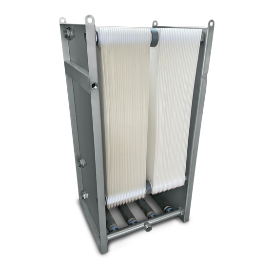
General Conditions of Purchase and Sale. Intended use: BIO-CEL EASY is designed for the treatment of municipal and industrial wastewater. BIO-CEL EASY is not designed for the filtration of food materials, drinking water or flow different from wastewater as mentioned above. Figure 1. BIO-CEL ®... -
Page 6: Handling And Interim Storage
Handling and Interim Storage The following are recommendations for safe storage and transport of BIO-CEL ® EASY prior to installation. Please make sure that the required materials are available on site. Caution: Transport with complete packaging only. Keep module in original packaging for further storage and transportation purposes and to move module to location of installation. -
Page 7: Product Description
EASY is a small but mighty MBR system built for customers whose water treatment needs fall into the 10 – 100 m ‘sweet spot’ for the modules. This simple and efficient MBR module is easy to design, assemble, connect, move, and expand in any customer facility. The BIO-CEL EASY module fits perfectly in the filtration tank: BIO-CEL EASY TANK. -
Page 8: Accessories & Spare-Parts
No spare parts are typically required for BIO-CEL EASY within the first five years of operation. If spare parts are needed, they may be ordered as per the Table 4. -
Page 9: Process Description
The performance of systems using BIO-CEL EASY depends on the whole process including pre-treatment, biological treatment process and mixed liquor quality. The mixed liquor filtered by the systems using BIO-CEL EASY must meet the quality requirements listed in table 5. This list is intended for municipal wastewater treatment and additional criteria may be required for other applications. - Page 10 Table 5. Characteristics of a well-working biology Parameter Acceptable Range Target Comments 5-40°C 10-30°C Lower temperatures will inhibit the bacteria and cause Temperature (41-104°F) (50-86°F) insufficient BOD/COD removal lower than MLSS Biology 6-10 g/L membrane tank 6-10 g/L It may be required to adjust RAS flow rate to ensure the limits MLSS Membrane Tank <...
-
Page 11: Filtration Process
For some venting options, the possibility for regular backwash is mandatory. Please make sure a suitable venting option is used. BIO-CEL EASY produces very high permeate water quality. The pore sizes of the BIO-CEL EASY membrane are selected such that all particulate materials (e.g. suspended solids) are rejected. However, dissolved and soluble materials such as dissolved organics, dissolved phosphorous, or nitrates must be converted to a solid form in order to be removed by the membranes. -
Page 12: Cleaning Process
Table 7. Achievable permeate quality Effluent Quality Parameter Expected Permeate Quality Achievable Permeate Quality Equal to soluble BOD concentration in mixed liquor < 1 mg/L < 5 mg/L < 2 mg/L Turbidity < 0.5 NTU < 0.2 NTU < 3 <... - Page 13 Table 8. General chemical cleaning data Parameter Units pH Range (Operation/Cleaning) 2-11 Temperatures (Operation/Cleaning) 5-40°C (41-104°F) Sodium Hypochlorite Target Concentration 200-2000 mg/L Total Chlorine Resistance 1,000,000 ppm•hours Hydrogen Peroxide Target Concentration 0.5-1 wt% Citric Acid Target Concentration 0.2-1 wt % Total Soaking Time 1-24 hours Chemical Fill Volume without Piping...
- Page 14 The main steps of the (extended) maintenance cleaning procedure are summarized in Table 10. Please note that this procedure is the most efficient way for maintenance cleaning whereas less automated systems may use one initial dosing time and a few additional dosing times.
- Page 15 In most cases, a recovery clean is performed with sodium hypochlorite and citric acid. Depending on the type of feedwater and the degree of fouling and scaling, a second chemical clean with sodium hypochlorite after the citric clean may be necessary. The main steps of the recovery cleaning procedure are summarized below.
-
Page 16: Process Design
Process Design BIO-CEL EASY P&ID & FUNCTIONAL DESCRIPTION Figure 4 shows a simplified P&ID of the MBR process (considering only nitrification as a biological step - pre-treatment and denitrification is not shown here). Figure 4. Simplified P&ID A list of all components and instruments according to the simplified P&ID in Figure 4 is given in Table 12. Please refer to Appendix 1 for the operational sequence chart of the filtration process considering a set-up as given in Figure 4 and a nomenclature as per Table 12. - Page 17 In the above cases, the tank will immediately proceed to STANDBY. The permeate pump P04 and recirculation pump P05 ramp down and Vx1-01 closes. To prevent sludge settling, the blower G02 operates for 5 minutes every 30 minutes. If the STANDBY triggers no longer exist and a start trigger is active, the tank proceeds into FILTRATION. FILTRATION In FILTRATION mode, Vx1-01 is open and the permeate pump P04 is running in the forward direction.
- Page 18 Table 12. Nomenclature of components & instruments of the given P&ID TAG-# Description Unit Blower for biology Blower for membrane tank Inflow pump to biology (project specific) Dosing pump for chemicals (alkaline cleaner) Dosing pump for chemicals (acidic cleaner) Process permeate pump (reversible for filtration and backwash) Recirculation pump (in membrane tank, not required if membrane modules are installed in biology) Drain pump (removal of excess sludge)
-
Page 19: Equipment & Tank Design
EQUIPMENT & TANK DESIGN Table 13 shows the most important design parameters with required equipment and tank sizes for different loads of municipal wastewater. Flow and flux rates are assuming filtration tank influent values as per Table 5. Table 13. Design parameters, equipment, and tank sizes for different loads of municipal wastewater Units Daily Average Flow m³/d... - Page 20 Table 14 shows the most important design parameters and required equipment and tank sizes for different loads of industrial wastewater. Industrial wastewater often shows higher amounts of non-biodegradable substances, which may lead to more fouling. Flow and flux rates are therefore lower compared to municipal wastewater. However, if the filtration tank influent values are as per Table 5, flow rates and fluxes of Table 13 can be applied for this application, as well.
- Page 21 Figure 5. Examples of venting tank piping Figure 6. Correct positioning of a venting unit BIO-CEL® EASY | USER MANUAL MANN+HUMMEL Water & Fluid Solutions | REVISION DATE: 09/06/2021...
-
Page 22: Commissioning
Commissioning Commissioning consists mainly of three steps: Pre-commissioning (preparation for water commissioning) Water commissioning and sludge seeding (including successful automatic run with water and sludge seeding of aeration tanks) Post-commissioning check PRE-COMMISSIONING The pre-commissioning has the goal of a proper module installation and assures a ready system for the water commissioning. Complete installation, pressure testing, cleaning, and purging of all facility systems (including chemical delivery systems). -
Page 23: Water Commissioning
12. Fill the filtration tank with water to a minimum of 5 cm above the top of the membranes. Caution IF FILLING THE MEMBRANE TANK IS NOT POSSIBLE, PLEASE ENSURE THAT THE MODULES ARE COVERED IN A WAY TO PROTECT AGAINST DIRECT SUNLIGHT AND RAIN. -
Page 24: Post-Commissioning Check
12. Start seeding the system. Important information ALL THE ACTIVATED SLUDGE AND WASTEWATER THAT IS INTRODUCED INTO THE PLANT MUST BE PUMPED THROUGH THE INFLUENT SCREENS TO ENSURE THAT NO HAIR, FIBER, OR DEBRIS ENTERS THE BIOREACTORS. COMMISSIONING CAN BE PERFORMED WITHOUT SEEDING, BUT THIS MAY TAKE SIGNIFICANTLY LONGER TO GET TO THE TARGET MLSS. -
Page 25: Performance Monitoring
Performance Monitoring PERMEABILITY MONITORING Performance monitoring of the entire MBR system is essential for a proper and safe operation. Permeability is the optimum parameter for monitoring the performance of an MBR plant. Permeability is the product flow (flux) through the membrane divided by the applied pressure. -
Page 26: Monitoring Diffuser Performance
Optimum Operating Range Decreased Permeability Range PERMEABILITY RANGE PERMEABILITY PERMEABILITY > 130 L/(m ·h·bar) ≤ 130 L/(m ·h·bar) > 5.2 GFD/psi ≤ 5.2 GFD/psi TIME RANGE OPERATION Ongoing Max. 10 days Frequency to maintain optimum operating range Optional in Case of Clogging Dewatering Maintenance... -
Page 27: Decommissioning And Storage
® EASY modules. When BIO-CEL EASY modules are not operating, they may be left submerged in mixed liquor in standby mode (interval aeration). This should be programmed into the PLC to ensure it is done automatically. After the membranes are wetted, they should be kept wet and should not be allowed to freeze. - Page 28 Table 15. Procedure for long-term storage of BIO-CEL® membrane modules Step Procedure Perform a recovery cleaning with sodium hypochlorite and citric acid and make sure that the membranes are clean and free of any debris or sludge. Prepare a preservative solution consisting of 20% glycerin and 3% sodium benzoate. This batch can be either prepared in the membrane tank or in an external tank.
-
Page 29: Disassembly & Disposal
Diffusers are made of PP with a silicon hose and can be demounted and disposed of separately if required. RETURNING DAMAGED MODULE Before returning BIO-CEL EASY modules, approval by MANN+HUMMEL WFS is required. Returned products without prior notification will be rejected. -
Page 30: Appendix 1: Operational Sequence Chart
Appendix 1: Operational Sequence Chart Tag Types: O - Open or on position in Auto M - Manually opened by operator X - Valve or motor is closed or off in Auto Opearting Mode R - Pump reverses direction T - Valve is throttling in Auto C - Vavle cycles through open and close sequence LS - Valve or pump keeps the last state (open/close;... - Page 31 Tag Types: O - Open or on position in Auto M - Manually opened by operator X - Valve or motor is closed or off in Auto Opearting Mode R - Pump reverses direction T - Valve is throttling in Auto C - Vavle cycles through open and close sequence LS - Valve or pump keeps the last state (open/close;...
Need help?
Do you have a question about the BIO-CEL EASY and is the answer not in the manual?
Questions and answers