Table of Contents
Advertisement
Available languages
Available languages
Quick Links
Advertisement
Chapters
Table of Contents

Related Manuals for hoxter HOS

Summary of Contents for hoxter HOS
- Page 1 User manual / Bedienungsanleitung / Uživatelský manuál...
- Page 3 EN / HOS User manual DE / HOS Bedienungsanleitung / HOS Uživatelský manuál...
- Page 5 Installation company Name Company name Address Address Phone No. Phone No. The end user has been made familiar with the operating and safety instructions of the combustion control HOS U and confirms their compliance. Date and signature Date and signature...
- Page 7 Installation company Name Company name Address Address Phone No. Phone No. The end user has been made familiar with the operating and safety instructions of the combustion control HOS U and confirms their compliance. Date and signature Date and signature...
-
Page 9: Table Of Contents
· The handover certificate should be provided to an authorised to the chimney sweeper upon request. · The HOS combustion control has been tested in TÜV SÜD laboratories and has been approved for the German market by the technical authority DIBt – Deutsches Institut für Bautechnik. -
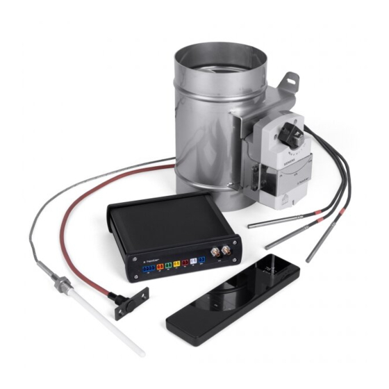
Page 10: Package Content
** DIN rail version supplied as standard, on customer‘s request the socket switch version available 3. Description of the device Electronic combustion control HOS is a device containing some of the following modules or their combination: · Module A – electronic combustion control – chapters related with this module are marked A ·... - Page 11 1 / / HOS Connection - MODULE A 3.2 Description of the function of primary water cycle control – MODULE W Module W (fig. 2) regulates the circulation pump depending on the temperature values measured by the heat sensors. The switching of the circulation pump (A) by the switch (7) is controlled based on ratio of values measured by heat sensors in the heat exchanger (4) and in the accumulation tank (5) and (6).
- Page 12 The wireless display (4) shows the current difference between the room pressure (B) and the pressure in the flue gas path (2) as well as the status of the ventilation unit (A). fig. 3 / HOS connection - MODULE U 12 I EN...
-
Page 13: Description Of The Connectors And The Control Unit
3. Connect the control unit (with the provided power adapter) into the 230 V power supply (fig. 5). 4. HOS electronic control has now been installed and you can move to the SET-UP phase. 5. The prerequisite for the proper functioning of HOS is the correct connection and proper operation of all connected components. MODULE U... - Page 14 U Orange indicates: ventilation device temporarily switched off indicates: ventilation device permanently switched off / module U malfunction (error number on the display) fig. 5 / Face 2 of HOS regulation and connection diagram, description of HOS signalling 14 I EN...
-
Page 15: Set-Up
5. Set-up 5.1 Wireless display and control unit pairing A W U For pairing wireless display and control unit, follow the instructions bellow (fig. 6): 1. Make sure all the components are properly connected to the control unit and that the diodes on its back does not indicate any error. In case of any error message, solve the error first in order to continue the pairing procedure. - Page 16 Only purchased modules are available in the main menu. The TEST module is displayed only when the fireplace insert is out of order (not burning). 5.3 Settings of the combustion control parameters (MODUL A) 1. Choose MODUL A in the HOS main menu to open the combustion control settings MODUL A T-START 2.
- Page 17 6. Select and confirm with the OK button to return to the main menu. 5.4 Settings of the circulation pump parameters (MODUL W) 1. Choose MODLE W in the HOS main menu to open the circulation pump settings MODUL W KP-START...
- Page 18 A W U 1. Choose TEST in the HOS main menu to open the test settings. The TEST menu is only available when no other module is activated and the temperature in the fireplace unit is lower than 35 °C.
-
Page 19: Operating
6. Operating 6.1 Wireless Display A W U The wireless display (fig. 8) consists of two parts, the upper (information) and the lower (control). Device status is displayed in the upper part of the display. The bottom of the display is touch-sensitive and is used to change the displayed information. To turn the wireless display on, take it in your hands (motion control). - Page 20 6.2 Displayed information The wireless display consists of two parts, the upper information and the lower control. Device status information is displayed at the top of the display. The bottom of the display is touch-sensitive and is used to change the displayed information. Circulation pump status Pump status If the symbol is on, the hot water circulation pump is in operation.
- Page 21 The temperature in the burning chamber is monitored because of possibility of accidental burn of the rest fuel. If accidental re-ignition occurs, the device opens the air supply flap. 5 Pa Pressure difference Shows the current difference between room pressure and flue gas pressure. The purpose is to ensure sufficient supply of the appliance with combustion air and safe exhaust of combustion gas.
- Page 22 Notifications and alerts A W U User will be informed through following symbols in case of unexpected situation. Weak signal Symbol indicates a signal loss between the control unit and the display. Follow “troubleshooting” on the next page. Opened door Informs that the fire chamber door is open.
-
Page 23: Troubleshooting
7. Troubleshooting Affected Error Cause Solution module code Check the connection of the temperature sensor. Check if the connector colour matches the cable colour. E01 - 01 Temperature sensor error If everything is correct, replace the sensor with a new one. Restart the control unit (press the SYS button for 3 seconds). -
Page 24: Warranty
8. Warranty The warranty period for electronic regulation HOS and its components is 24 months from the date of installation of the device. The warranty does not cover mechanical damage, damage due to exposure of components to temperatures higher than their defined maximum values and damage caused by improper handling in violation of the instructions. - Page 25 Protokolls gelöst werden. Die in diesem Protokoll aufgezeichneten Werte dürfen vom Anlagenbetreiber nicht geändert werden. Dieses Protokoll hat der Anlagenbetreiber für die Dauer des Betriebes der HOS U oder bis zur nächsten. Parameteränderung, die ausschließlich von einer Fachfirma ausgeführt werden darf, aufzubewahren. Für den Fall einer Parameteränderung ist zwingend ein neues Protokoll zu erstellen.
- Page 27 Protokolls gelöst werden. Die in diesem Protokoll aufgezeichneten Werte dürfen vom Anlagenbetreiber nicht geändert werden. Dieses Protokoll hat der Anlagenbetreiber für die Dauer des Betriebes der HOS U oder bis zur nächsten. Parameteränderung, die ausschließlich von einer Fachfirma ausgeführt werden darf, aufzubewahren. Für den Fall einer Parameteränderung ist zwingend ein neues Protokoll zu erstellen.
-
Page 29: Sicherheitshinweise
· Auf Anfrage sind dem bevollmächtigten Bezirksschornsteinfegermeister (BSFM) die protokollierten Einstellungen vorzulegen. · Die Steuerung HOS wurde vom TÜV SÜD geprüft und für den deutschen Markt wurde sie durch das DIBt zugelassen und zertifiziert. 1.2 Gefährdung durch Luftmangel oder schadhafte Abgasleitungen Für Ihre Feuerstätte ist immer eine ausreichende Menge an Verbrennungsluft und ein funktionsfähiger Schornstein sicherzustellen. -
Page 30: In Der Verpackung Enthaltene Komponenten
1.3 Verletzungsgefahr durch Stromschlag · Der Anschluss an das Stromnetz darf nur von einer Fachfirma durchgeführt werden. · Die elektrischen Leitungen dürfen bei der Installation der Steuerung HOS, einschl. der Peripheriegeräte, nicht unter Spannung stehen. Eine unsachgemäße Installation kann zu einem Stromunfall führen. - Page 31 Bei der Version mit Funkdisplay (4) zeigt das Display den mit dem Temperaturfühler gemessenen Temperaturwert, die Position der Zuluftklappe und die Laufzeit des Abbrands an. Abb. 1 / Schaltung von HOS – MODUL A 3.2 Beschreibung der Funktion der Kesselkreisregelung – MODUL W Modul W (Abb.
- Page 32 Das Funkdisplay (4) zeigt die aktuelle Differenz zwischen dem Druck im Raum (B), wo das Gerät installiert ist, und dem Druck im Abgasweg (2) sowie den Betriebszustand der Lüftungseinrichtung (A) an. Abb. 3 / Schaltung von HOS – MODUL U 32 I DE...
-
Page 33: Inbetriebnahme Und Beschreibung Der Steuerung Hos
3. Die Steuereinheit der elektronischen Steuerung mit dem mitgelieferten Netzstecker an das Stromnetz (230 V) anschließen (Abb. 5). 4. Die elektronische Steuerung HOS ist installiert und die Phase Einstellung kann eingeleitet werden. 5. Voraussetzungen für den einwandfreien Betrieb von HOS sind der korrekte Anschluss und die korrekte Funktion aller angeschlossenen Komponenten. - Page 34 Lüftungseinheit vorübergehend ausgeschaltet signalisiert: Lüftungseinheit dauerhaft ausgeschaltet / Fehler Modul U (Fehlercode auf Display) Abb. 5 / Rückseite der elektronischen Steuerung HOS und Schema für den Netzanschluss, Erläuterungen zu den Bedienungselementen und zur Signalisierung von HOS. 34 I DE...
-
Page 35: Einstellungen
5. Einstellung 5.1 Paarung Funkdisplay und Steuereinheit A W U Bei der Paarung des Funkdisplays und der Steuereinheit, gehen Sie wie folgt vor (Abb. 6) 1. Vergewissern Sie sich, dass alle Komponenten mit der Steuereinheit korrekt verbunden sind und die LED’s auf deren Rückseite keinen Fehler melden. - Page 36 TEST wird auf dem Display nur dann angezeigt, wenn der Kamineinsatz außer Betrieb ist (kein Feuer). 5.3 Einstellung der erforderlichen Werte des Moduls für Abbrandsteuerung (MODUL A) 1. Durch Bestätigen der Wahl MODUL A wird im Hauptmenü HOS die Einstellung „Modul Abbrandsteuerung“ geöffnet MODUL A T-START 2.
- Page 37 Taste OK bestätigen, kommen Sie ins Hauptmenü Einstellung zurück. 5.4 Einstellung der erforderlichen Werte des Moduls für Kesselkreisregelung (MODUL W) 1. Durch Bestätigen der Wahl MODUL W wird im Hauptmenü HOS die Einstellung „Modul Kesselkreisregelung“ geöffnet. MODUL W...
- Page 38 A W U 1. Wenn TEST angewählt und bestätigt wird, öffnet sich im Hauptmenü HOS das Menü Funktionstest des Gerätes. Das Menü TEST ist nur dann aktiv, wenn keine andere Steuerung läuft und die Temperatur im Gerät 35 °C nicht übersteigt.
-
Page 39: Betrieb
6. Betrieb 6.1 Funkdisplay A W U Das Funkdisplay (Abb. 8) besteht aus zwei Bereichen, dem oberen Anzeigebereich und dem unteren Bedienungsbereich. Im oberen Bereich des Displays werden Informationen über den Zustand des Gerätes angezeigt. Der untere Bereich ist ein Tastfeld, das zur Änderung der angezeigten Informationen dient. - Page 40 6.2 Angezeigte Informationen Symbol Zustand der Pumpe Zustand der Kesselkreispumpe wenn dieses Symbol leuchtet, ist die Kesselkreispumpe in Betrieb. Grundinformationsmenü Beim normalen Betrieb werden auf dem Display die folgenden Informationen angezeigt. Zwischen den einzelnen Informationen kann man mit den Pfeiltasten auf dem Display wechseln. 150 °C Temperatur im Feuerraum aktuelle Temperatur im Feuerraum, gemessen durch den Abgastemperaturfühler.
- Page 41 Die Temperatur im Feuerraum wird wegen einem etwaigen Wiederentflammen der Brennstoffreste weiterhin verfolgt. Sollte es zum ungewollten Entflammen kommen, so öffnet das Gerät die Zuluftklappe. 5 Pa Druckunterschied aktuelle Differenz zwischen dem Druck im Innenraum und dem Druck im Abgasweg. Der Zweck ist es, eine ausreichende Versorgung des Gerätes mit der Verbrennungsluft und eine sichere Abgasabführung sicherzustellen.
- Page 42 Hinweise und Alarm A W U Sollte ein Ereignis eintreten, über das der Benutzer informiert werden sollte, wird auf dem Display eins der folgenden Symbole angezeigt. Schwaches Signal informiert darüber, dass das Signal zwischen dem Display und der Steuereinheit des Gerätes schwach ist. Tür ist geöffnet informiert darüber, dass die Tür des Gerätes geöffnet ist.
-
Page 43: Fehler Und Problemlösung
7. Fehler und Problemlösung Auf dem Elektronikmodul, Display Ursache Fehlerbehebung das den Fehler angezeigter meldet Fehlercode Prüfen Sie den Anschluss des Abgastemperaturfühlers. Die farbliche Markierung der Kabel muss identisch mit der farblich markierten Steckerbelegung sein. Wenn der Anschluss in E01 - 01 Fehler Abgastemperaturfühler Ordnung ist, führen Sie einen Neustart der Steuereinheit durch (die Taste SYS 3 Sekunden gedruckt halten). -
Page 44: Garantie
8. Garantie Die Garantiezeit für die elektronische Steuerung HOS und für die dazugehörigen Komponenten beträgt 24 Monate ab dem Tag der Installation der Vorrichtung. Die Garantie bezieht sich nicht auf mechanische Beschädigungen, Schäden, die dadurch entstanden sind, dass die Komponenten Temperaturen ausgesetzt wurden, die die definierten Grenzwerte überstiegen haben, und auf Schäden,... - Page 45 Hodnoty zaznamenámy v tomto protokolu nesmí být změněny koncovým uživatelem. Koncový uživatel má povinnost uschovat tento protokol po dobu provozování zařízení HOS U nebo do další změny parametrů, které může provést pouze odborná firma, která musí následně vystavit protokol nový. Zaznamenané nastavení musí být na vyžádání...
- Page 47 Hodnoty zaznamenámy v tomto protokolu nesmí být změněny koncovým uživatelem. Koncový uživatel má povinnost uschovat tento protokol po dobu provozování zařízení HOS U nebo do další změny parametrů, které může provést pouze odborná firma, která musí následně vystavit protokol nový. Zaznamenané nastavení musí být na vyžádání...
- Page 49 · Na vyžádání zašlete prosím zprávu o uvedení do provozu oprávněnému kominíkovi. · Regulace HOS byla testována v laboratořích TÜV SÜD a pro německý trh byla schválena u společnosti DIBt. Při uplatňování záruky je nutné doložit potvrzený protokol uvedení do provozu.
- Page 50 **standardně dodávána verze s upevněním na DIN lištu, volitelně i verze do zásuvky 3. Popis funkce regulace HOS Elektronická regulace HOS je zařízení obsahující některý z následujících modulů nebo jejich kombinaci: · Modul A – regulace hoření – kapitoly týkající se tohoto modulu jsou označeny A ·...
- Page 51 1 / Zapojení HOS – MODUL A 3.2 Popis funkce regulace kotlového okruhu – MODUL W Modul W (obr. 2) reguluje oběhové čerpadlo v závislosti na hodnotách teplot naměřených teplotními čidly. Spínání oběhového čerpadla (A) spínačem (7) je řízeno na základě nastaveného poměru hodnot naměřených teplotními čidly ve výměníku (4) a v akumulační...
- Page 52 řídící jednotce, čtvrtý restart musí být proveden výhradně na řídící jednotce zařízení. Bezdrátový displej (4) zobrazuje aktuální rozdíl mezi hodnotou tlaku v místnosti (B) se spotřebičem a tlaku ve spalinové cestě (2) a stav zařízení vzduchotechniky (A). obr. 3 / Zapojení HOS – MODUL U 52 I CZ...
- Page 53 3. Zapojte řídící jednotku regulace pomoci přiloženého napájecího adaptéru do elektrorozvodné sítě 230V (obr. 5). 4. Regulace HOS byla nainstalována a můžete přejít do fáze NASTAVENÍ. 5. Předpokladem pro správné fungování HOS je správné připojení a správná funkce všech připojených komponentů. MODUL U DK - objímka kouřovodu...
- Page 54 červená zařízení vzduchotechniky trvale vypnuto / chyba modulu U (číslo chyby na displeji) obr. 5 / Čelo 2 regulace HOS a schéma připojení napájení, vysvětlení ovládacích prvků a signalizace HOS 54 I CZ...
- Page 55 5. Nastavení 5.1 Párování bezdrátového displeje a řídící jednotky A W U Při párování bezdrátového displeje a řídící jednotky postupujte následovně (obr. 6) 1. Ujistěte se, zda jsou všechny komponenty správně propojeny s řídící jednotkou a diody na její zadní straně nesignalizují žádnou chybu.
- Page 56 Modul TEST je zobrazován na displeji pouze tehdy, když je krbová vložka mimo provoz (nehoří v ní). 5.3 Nastavení požadovaných hodnot modulu regulace hoření (MODUL A) 1. Potvrzením volby MODUL A se v hlavním menu HOS otevře nastavení modulu regulace hoření MODUL A T-START 2.
- Page 57 6. Volbou a potvrzením tlačítkem OK se vrátíte do hlavního menu nastavení. 5.4 Nastavení požadovaných hodnot modulu regulace kotlového okruhu (MODUL W) 1. Potvrzením volby MODUL W se v hlavním menu HOS otevře nastavení modulu regulace kotlového okruhu MODUL W KP-START...
- Page 58 5.6 Ověření funkčnosti zapojení A W U 1. Potvrzením volby TEST v hlavním menu HOS se otevře menu testování funkce zařízení. Menu TEST je aktivní pouze v případě, kdy není spuštěna žádná jiná regulace a ve spotřebiči není dosažena teplota > 35 °C.
- Page 59 6. Provoz 6.1 Bezdrátový displej A W U Bezdrátový displej (obr. 8) je tvořen ze dvou částí, horní informační a dolní ovládací. V horní části displeje jsou zobrazovány informace o stavu zařízení. Spodní část displeje je dotyková a slouží ke změně zobrazovaných informaci. Bezdrátový...
- Page 60 6.2 Zobrazované informace Bezdrátový displej je tvořen ze dvou částí, horní informační a dolní ovládací. V horní části displeje jsou zobrazovány informace o stavu zařízení. Spodní část displeje je dotyková a slouží ke změně zobrazovaných informaci. Stav čerpadla Stav oběhového čerpadla Pokud symbol svítí, je oběhové...
- Page 61 Teplota v topeništi je dále sledována pro případné nechtěné rozhoření zbytku paliva. Pokud by k nechtěnému rozhoření došlo, zařízení otevře klapku přívodu vzduchu. 5 Pa Rozdíl tlaku Zobrazuje aktuální rozdíl tlaku v místnosti a tlaku ve spalinové cestě. Účelem je zabezpečení dostatečného zásobení spotřebiče spalovacím vzduchem a bezpečný...
- Page 62 Upozornění a alarmy A W U Pokud nastane událost, o níž by měl být uživatel informován, zobrazí se na displeji některý z následujících symbolů. Slabý signál Zobrazením informuje o slabém signálu mezi displejem a řídící jednotkou zařízení. Otevřená dvířka Zobrazením informuje o otevřených dvířkách spotřebiče. Přetopení...
- Page 63 7. Chyby a řešení problémů Modul Kód chyby elektroniky zobrazený Příčina Odstranění poruchy hlásící chybu na displeji Zkontrolujte připojení konektoru spalinového teplotního čidla. Zkontrolujte shodnost barvy vodiče s barevným označením Chyba spalinového teplotního E01 - 01 na konektoru. Proveďte restart řídící jednotky. Pokud tímto čidla nedojde k odstranění...
- Page 64 8. Garance Záruční doba na elektronickou regulaci HOS a její komponenty je 24 měsíců od data instalace zařízení. Záruka se nevztahuje na mechanické poškození, poškození z důvodu vystavení komponentů teplotám vyšším než jejich definovaným maximálním hodnotám a poškození vzniklá neodbornou manipulaci v rozporu s návodem. Instalace elektronické regulace HOS musí provádět proškolená...
- Page 68 HOXTER GmbH Haidmühlweg 5 92665 Altenstadt an der Waldnaab DEUTSCHLAND Tel.: 0049 (0)9602 9447 944 E-mail: info@hoxter.de HOXTER a.s. Jinacovice 512 66434 Jinacovice CZECH REPUBLIC Tel.: +420 518 777 701 E-mail: info@hoxter.eu www.hoxter.eu Stand 07/2021 M1000327 Changes of the stated data and errors reserved.
Need help?
Do you have a question about the HOS and is the answer not in the manual?
Questions and answers