Table of Contents
Advertisement
Quick Links
INFORMATION AND OPERATING INSTRUCTIONS
INFORMATION ET DIRECTIVES D'UTILISATION
A-English
B-Español
C-Français
PRECAUCIÓN: NO UTILICE LA MÁQUINA HASTA HABER LEÍDO
IMPROPER USE OF THE MACHINE WILL VOID THE WARRANTY
EL USO INCORRECTO DE LA MÁQUINA ANULARÁ LA GARANTÍA
UNE UTILISATION INCORRECTE DE LA MACHINE ANNULERA LA GARANTIE
No part of this manual may be reproduced or used in any form or by any means (i.e. graphic, electronic, photocopying or electronic
retrieval systems) without the express written permission of HydraMaster. Specifications and information in this document are
subject to change without prior notice. All rights reserved. © 2021 HydraMaster
INFORMACIÓN E INSTRUCCIONES DE USO
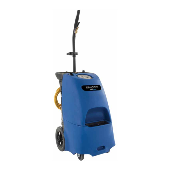
PEX 500-Item #635K
Owner's Manual
MODEL: 56113150
HydraMaster
11015 47
Mukilteo, Washington 98275
56044659 Rev. B, Jan 2021
CAUTION: DO NOT OPERATE MACHINE UNTIL YOU HAVE READ
ALL SECTIONS OF THIS INSTRUCTION MANUAL
TODAS LAS SECCIONES DE ESTE MANUAL DE INSTRUCCIONES
ATTENTION : N'UTILISEZ PAS LA MACHINE AVANT D'AVOIR LU
TOUTES LES SECTIONS DU PRÉSENT MANUEL
Avenue West
th
Advertisement
Table of Contents

Related Manuals for HydraMaster PEX 500 635K

Summary of Contents for HydraMaster PEX 500 635K
- Page 1 No part of this manual may be reproduced or used in any form or by any means (i.e. graphic, electronic, photocopying or electronic retrieval systems) without the express written permission of HydraMaster. Specifications and information in this document are subject to change without prior notice. All rights reserved. © 2021 HydraMaster...
- Page 2 This page intentionally left blank. RX-20 / CMX-20 Owner’s Manual - 2 PEX 500 - SP Owner’s Manual - 2...
-
Page 3: Table Of Contents
Table of Contents Introduction .........................5 Parts and Service ......................5 Modifications .......................5 Nameplate ........................5 Uncrating the Machine ....................5 Cautions and Warnings ....................5 Grounding Instructions ....................7 Know Your Machine ....................9 Know Your Switch Plate .................... 11 Preparing the Machine for Use .................12 Operating the Machine ....................12 After Using the Machine ....................15 Maintenance Schedule....................15... - Page 4 This page intentionally left blank. RX-20 / CMX-20 Owner’s Manual - 4 PEX 500 - SP Owner’s Manual - 4...
-
Page 5: Introduction
Modifications and additions to the cleaning machine which affect capacity and safe operation shall not be performed by the customer or user without prior written approval from HydraMaster LLC. Unapproved modifications will void the machine warranty and make the customer liable for any resulting accidents. - Page 6 IMPORTANT SAFETY INSTRUCTIONS This machine is only suitable for commercial use, for example in hotels, schools, hospitals, factories, shops and offices other than normal residential housekeeping purposes. When using any electrical appliance, basic precautions should always be followed, including the following: NOTE: Read all instructions before using this machine.
-
Page 7: Grounding Instructions
• High pressure jets can be dangerous if subject to misuse. The jet must not be directed at persons, live electrical equipment or the machine itself. • Do not use the machine within range of persons unless they wear protective clothing. •... - Page 8 WARNING! • If an extension cord is used, the plug and socket must be of watertight construction. • Inadequate extension cords can be dangerous. • Extension cords must be 12/3 and no longer than 50 feet. Replace the cord or unplug immediately if the ground prong becomes damaged.
-
Page 9: Know Your Machine
KNOW YOUR MACHINE Solution Hose Quick Disconnect Solution Tank Fill Opening Vacuum Hose Barb Drain Hose Handles Roller Balls Wheel Castor Solution Filter 10 Recovery Tank Shutoff Float 9 - RX-20 / CMX-20 Owner’s Manual 9 - PEX 500 - SP Owner’s Manual... - Page 10 KNOW YOUR MACHINE (CONTINUED) 11 Recovery Tank Lid 12 Switch Plate 13 Wand Storage Clip 14 Pressure Adjustment Knob 15 Pressure Gauge 16 Pressure Relief Valve 17 Cord Retainer Straps (four) 18 Hour Meter (Optional) 19 Wand Retainer Bracket 20 Power Cords 21 Hose Hangers (two) RX-20 / CMX-20 Owner’s Manual - 10 PEX 500 - SP Owner’s Manual - 10...
-
Page 11: Know Your Switch Plate
KNOW YOUR SWITCH PLATE Solution Pump Switch - This switch turns the solution pump ON and OFF. Vacuum Switch - This switch turns the first of the two vacuum motors ON and OFF. Vacuum Switch - This switch turns the second of the two vacuum motors ON and OFF. Circuit Indicator - When this light is on, it indicates that the two cords are on a separate circuit. -
Page 12: Preparing The Machine For Use
PREPARING THE MACHINE FOR USE See the diagrams in the “Know Your Machine” section. Inspect the machine, hoses, and cleaning tools for cleanliness and completeness. Screw the Recovery Tank Lid (11) closed. Ensure the drain cap is closed tightly. Pre-spray spots and heavy traffic areas before extracting with the detergent of your choice. Mix the pre-spray according to the detergent manufacturer’s directions. - Page 13 CAUTION! Always make sure the float is clean and travels freely before turning on the machine. A float that is stuck will cause the vacuum motor to suck in water, resulting in vac motor damage. The recovery tank has a Recovery Tank Shutoff Float (10) to block the vacuum system when the recovery tank is full. You can tell when the float closes by the sudden change in the sound of the vacuum motor.
- Page 14 OPERATING THE MACHINE RX-20 / CMX-20 Owner’s Manual - 14 PEX 500 - SP Owner’s Manual - 14...
-
Page 15: After Using The Machine
• *Check Carbon Brushes • * Have a Hydramaster service technician check the vacuum motor carbon brushes once a year or after 300 operating hours. Check the pump motor carbon brushes every 500 hours or once a year. IMPORTANT! Motor damage resulting from failure to service the carbon brushes is not covered under warranty. -
Page 16: Troubleshooting
Spraying too long. Try spraying for 12-15 seconds, or about three strokes. • Spray tips(s) too large. Use a maximum of two HydraMaster part number 000-076-122 spray tip(s). LOW HEAT Longer hose or larger diameter hose than recommended. Use a maximum of 25-foot-long ¼ inch hose for best results. - Page 17 17 - RX-20 / CMX-20 Owner’s Manual 17 - PEX 500 - SP Owner’s Manual...
-
Page 18: Water Flow Diagram
* = Optional, Not Included WATER FLOW DIAGRAM Water Flow Diagram BLUE = FRESH WATER GREEN = 500PSI WATER FLOW PURPLE = PRESSURE RELIEF RETURN TO TANK RED = 500PSI HEATED WATER FLOW PEX 500 - Water Flow Diagram BLUE = FRESH WATER Item Description Solution Tank... -
Page 19: Electrical Diagram
VAC 2 HEATER HEATER CHOKE COIL CHOKE COIL CHOKE COIL CHOKE COIL HEAT ELEMENT HEAT ELEMENT GRN/YEL BRN/WHT 19 - PEX 500 - SP Owner’s Manual HydraMaster PEX 500 19 - PEX 500 Owner’s Manual NOTES UNLESS OTHERWISE 5-13-10 DRAWN SPECIFIED... - Page 20 Assemblies and Parts Lists: 20 PEX 500 Owner’s Manual - 20 HydraMaster PEX 500...
-
Page 21: Assembly And Parts List
Assemblies and Parts Lists The following ServPro PEX 500 - Item #635K major assemblies are detailed in this section: Description ......................Page „ PEX 500 - Item #635K - Final Assembly and Parts List ......... 22 „ PEX 500 - 120V/60Hz - Pallet Assembly and Parts List ........24 „... - Page 22 Figure 1. PEX 500 - Item #635K Final Assembly REVISION DESCRIPTION 081-564 WAS 56383E31 081-563 WAS 56100705 & PART OF 081-564 SET; ADDED 56044717 1 2X 4339 4344 1 56380831 56113147 56384917 1 NOTE: 1 LABELS A 2 APPLY LA 56380692 1 2X 4339 PEX 500 - SP Owner’s Manual - 22...
- Page 23 REVISION DESCRIPTION CODE DATE CHKD APPVD 081-564 WAS 56383E31 10/28/2020 L.O.L. R.D.D. R.D.D. 081-563 WAS 56100705 & PART OF 081-564 SET; REVISION DESCRIPTION CODE DATE CHKD APPVD 01/06/2021 L.O.L. R.D.D. R.D.D. ADDED 56044717 081-564 WAS 56383E31 10/28/2020 L.O.L. R.D.D. R.D.D. PEX 500 - Item #635K Final Assembly Parts List 081-563 WAS 56100705 &...
- Page 24 Figure 2. PEX 500 - 120V/60Hz - Pallet Assembly PEX 500 - SP Owner’s Manual - 24...
- Page 25 WHEEL, 12" X 1" BLACK ON GRAY 1/2" AXLE VARIOUS 2092 VULCANIZED FIBRE - WASHER, 9/16" I.D. X 1" O.D. X 1/16" FIBER 115USP Figure 3. PEX 500 - 120V/60Hz - Pallet Assembly BLACK WASHER, 9/16" I.D. X 1" O.D. X 1/16" BRASS HALF HARD BRASS 31USP WASHER, 5/16"...
- Page 26 Figure 4. PEX 500 - 120V/60Hz - Pallet Assembly 50248A 56219932 56113086 50248A 56113085 56412277 50248A 56113087 56113080 56113110 56113078 56113063 56219932 56113079 50248A 56113077 PROPRIETARY INFORMATION 11015 47th Avenue West, Mukilteo, Washington 98275 PALLET SYSTEM - PEX 500-HM 120V / 60Hz PEX 500 - SP Owner’s Manual - 26 DRAWN P.T.
- Page 27 Figure 5. PEX 500 - 120V/60Hz - Pallet Assembly PROPRIETARY INFORMATION 11015 47th Avenue West, Mukilteo, Washington 98275 27 - PEX 500 - SP Owner’s Manual PALLET SYSTEM - PEX 500-HM 120V / 60Hz DRAWN P.T. 5/23/2019 SIZE PART NUMBER CHECKED R.D.D.
- Page 28 Figure 6. PEX 500 - 120V/60Hz - Item #635K Pallet Assembly PEX 500 - SP Owner’s Manual - 28...
- Page 29 Pallet System PEX 500 - 120V/60Hz - Assembly Parts List Item Part Number Description Item Part Number Description 56113058 ASSEMBLY, HEATER - COMPLETE-120V 2000W 56113021 HANGER, HOSE S/S 102-004-001 ASSEMBLY, MOTOR - PEX 500 120V/60Hz 56113046 HARNESS, MAIN 56113104 ASSEMBLY, PRESSURE RELIEF 56113079 HOSE ASSEMBLY, 1/4”...
- Page 30 Pallet System PEX 500 - 120V/60Hz - Assembly Parts List Item Part Number Description Item Part Number Description 000-143-333 SCREW, 1/4”-20UNC x 0.50” LG. S/S HEX HEAD 56004001 WASHER, 0.8” I.D.X1.1” O.D.X0.021” DIS SPR S/S 56003798 SCREW, 5/16”-18UNC X 1.25” LG. SOCKET HEAD 000-174-049 WASHER, 5/16”...
- Page 31 Figure 7. PEX 500 - SP - Solution System Assembly REVISION CODE DATE ITEMS MOUNTED INSIDE THE TANK DESCRIPTION DRAWING RELEASED 08/06/2020 ITEMS MOUNTED INSIDE THE TANK 7 2X BYPASS / RETURN HOSE FROM PALLET SYSTEM WASHER, 0.26" ID X 1" FLAT X 0.074 THK.
- Page 32 CODE DATE CHKD DESCRIPTION DRAWING RELEASED 08/06/2020 P.T. L.R.K. PEX 500 - SP - Solution System Assembly Parts List Item Part Number Description 905USP CASTER SWIVEL 4 GRAY NON MA 805USP CHAIN, 8” w/ D COUPLINGS BOTH ENDS 207A FILTER 40 MESH S/S 1/2NPT FEM 56113034 PLATE, HINGE 901A...
- Page 33 REVISION DESCRIPTION CODE DATE DRAWING RELEASED 8/6/2020 P.T. ADDED NOTES. 09/15/2020 L.O.L. Figure 8. PEX 500 - SP - Recovery System Assembly TANK, RECOVERY w/ FITTING- PEX 500 VARIOU BLUE ITEM IS ATTACHED SCREW, #8-32UNC X 1.125" LG. PHILLIPS S. STEE HEAD S/S TO ITEM FROM...
- Page 34 REVISION DESCRIPTION CODE DATE CHKD APPVD DRAWING RELEASED 8/6/2020 P.T. L.R.K. P.E. PEX 500 - SP - Recovery System Assembly Parts List ADDED NOTES. 09/15/2020 L.O.L. L.R.K. L.R.K. Item Part Number Description 56113039 ASSEMBLY, BALL FLOAT 1277 INSERT, 1-1/2” FPT X 1-1/2” HOSE 56105266 CAP, DRAIN HOSE 805USP...
- Page 35 052-102 WAS 164. 09/15/2020 L.O.L. L.R.K. L.R.K. Figure 9. PEX 500 - Syphon Hose For HHP-12 Assembly REVISION DESCRIPTION CODE DATE CHKD APPVD RELEASED DRAWING 6/18/2020 P.T. L.O.L. P.E. 052-102 WAS 164. 09/15/2020 L.O.L. L.R.K. L.R.K. PEX 500 - SYPHON HOSE FOR HHP-12 Assembly Parts List Item Part Number Description...
- Page 36 REVISION DESCRIPTION CODE DATE CHKD APPVD RELEASED DRAWING 9/21/2020 L.O.L. L.R.K. L.R.K. Figure 10. Heater- Complete - 120V 2000W Assembly ADDED NOTE 5. 10/28/2020 L.O.L. R.D.D. R.D.D. VERIFY CASTING HAS THE "4" STAMP NOTES: ASSEMBLY OF ITEMS: 2X 2 ,2X 7 &...
- Page 37 REVISION DESCRIPTION CODE DATE CHKD APPVD RELEASED DRAWING 9/21/2020 L.O.L. L.R.K. L.R.K. ADDED NOTE 5. 10/28/2020 L.O.L. R.D.D. R.D.D. PEX 500 - Heater - Complete -120V 2000W Assembly Parts List Item Part Number Description 000-052-084 ELBOW, 1/8” NPT STREET ELECT BUTT CONN 12 TO 14 STEP ELECT RING CONN 14-16 GA 4-6 2161 HEATER WRAP 1/2 FOAM FLAM...
- Page 38 PEX 500 - Motor - 120V/60Hz Assembly Parts List Figure 11. PEX 500 - Motor - 120V/60Hz Assembly Item Part Number Description REVISION DESCRIPTION CODE DATE CHKD APPVD 000-033-010 CLAMP, SIZE #32 HOSE RELEASE DRAWING. 09/15/2020 L.O.L. L.R.K. L.R.K. 1518 CLAMP, 3/4”...
- Page 39 REVISION DESCRIPTION CODE DATE CHKD APPVD 052-090 WAS 56113083; 09/16/2020 L.O.L. L.R.K. L.R.K. PEX 500 - Pressure Relief Assembly Parts List Figure 12. PEX 500 - Pressure Relief Assembly REVISION DESCRIPTION CODE DATE CHKD Item Part Number Description 56756739 ELBOW, 1/4 NPT X 3/8 BARB X 90° BRASS 052-090 WAS 56113083;...
- Page 40 REVISION DESCRIPTION CODE DATE RELEASE DRAWING; CHANGE 950D & 143-606 TO BE PART OF 950F; 037-009 WAS 56172230; 037-012 5/5/2020 L.O.L. WAS 56900902. 106-007 WAS 106-047; ADD WIRE COLORS. 01/06/2021 L.O.L. PEX 500 - Pump 120V-500PSI Assembly Figure 13. PEX 500 - Pump - 120V-500PSI Assembly Item Part Number Description...
- Page 41 PEX 500 - Swith Panel - 120V/60Hz Assembly Figure 14. PEX 500 - Switch Panel - 120V/60Hz Assembly Item Part Number Description REVISION DESCRIPTION CODE DATE CHKD APPVD 000-057-273 GASKET, ROCKER SWITCH 56113124 GASKET, SWITCH PLATE RELEASE DRAWING. 09/15/2020 L.O.L. L.R.K.
- Page 42 REVISION DESCRIPTION CODE DATE CHKD APPVD RELEASE DRAWING. 9/15/2020 L.O.L. L.R.K. L.R.K. DEL 1555; 033-151 WAS 1554; 169-250 WAS 945D; 12/03/2020 L.O.L. R.D.D. R.D.D. 143-168 WAS 143-080. Figure 15. PEX 500 - Unloader Valve Assembly PEX 500 Unloader Valve Assembly Item Part Number Description...
- Page 43 PEX 500 Ball Float Assembly Figure 16. PEX 500 - Ball Float Assembly REVISION DESCRIPTION CODE DATE CHKD APPVD Item Part Number Description WRAP THREADS ON WITH 3 1154 ADAPTER, 1-1/2” TRAP ABS RELEASE HM DRAWING. 10/14/2020 L.O.L. L.R.K. L.R.K. 1140 ELBOW, 1-1/2”...
-
Page 44: Year Limited Warranty
HydraMaster warrants to the original purchaser / user that this product is free from defects in workmanship and materials under normal use and service for a period of two (2) years from date of purchase. In addition,... -
Page 45: Warranty Registration
WARRANTY PROCEDURE To facilitate any possible warranty claims, register online at www.hydramaster.com/support/ warrantyregistration.aspx and fill out this form completely within 10 days of date of purchase. You must save your sales invoice so you can provide proof of purchase date. Please be sure to fill out distributor information, they will be able to supply proof of purchase date in the event you are unable to find your sales invoice.
Need help?
Do you have a question about the PEX 500 635K and is the answer not in the manual?
Questions and answers