
Subscribe to Our Youtube Channel
Related Manuals for CorroVenta HOMEVISION PRO

Summary of Contents for CorroVenta HOMEVISION PRO
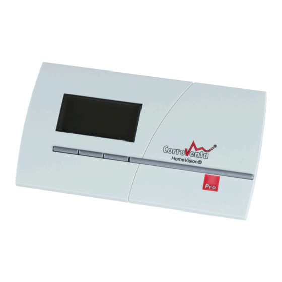
- Page 1 HOMEVISION® PRO Control System for VentoVind™ and crawl space dehumidifiers CTR STD-TT and CTR 300TT2 USER MANUAL...
-
Page 2: Table Of Contents
Diagnostics – VentoVind™, Fan test ......................30 Diagnostics – VentoVind™, Damper test ....................31 See overview of settings for all units, Crawl space ................... 32 See configuration overview for all units, VentoVind™ ................33 © Corroventa Avfuktning AB 2021.02 1 (44) - Page 3 Resetting to factory default ........................37 Remove unit .............................. 38 Alarms and service reminders ........................39 Interpreting the USB log ........................... 41 Maintenance and service .......................... 42 Troubleshooting ............................43 Technical data ............................44 © Corroventa Avfuktning AB 2021.02 2 (44)
-
Page 4: Area Of Use
Area of use HomeVision® Pro has been developed and designed for wireless control and monitoring of Corroventa CTR STD-TT and CTR 300TT2 crawl space dehumidifiers as well as VentoVind™, adaptive ventilation of cold attic spaces. There are two versions of control unit, one for crawl spaces and one for VentoVind™ but the control panel is common and compatible to both. -
Page 5: Manufacture Directive
Corroventa AB's written consent. Any comments regarding the content of this document must be sent to: Corroventa Avfuktning AB Tel: +46 (0)3637 12 00 Mekanikervägen 3... -
Page 6: Safety Information
Do not damage the cables. They must nor run through water or over sharp edges. HomeVision® and VentoVind™ must not be used with accessories other than those described in this manual or approved by Corroventa Avfuktning AB. Contact the supplier of this dehumidifier for further advice on the safety and use of the product. -
Page 7: Relative Humidity And Its Impact On Materials
The chart below is not to scale, it has the sole purpose of clarifying the principle and parameters. Dehumidification on Alarm level Alarm +%RH Hysteresis Upper/Lower: Setpoint value Dehumidification off Temperature © Corroventa Avfuktning AB 2021.02 6 (44) -
Page 8: Mould Index Regulation
The chart is not to scale but is intended only to clarify the principle and actual parameters. %-RH Dehumidification on Mould index curve Alarm, +%RH Safety margin Hysteresis Upper RH-MGI Hysteresis Lower Dehumidification off Temperature © Corroventa Avfuktning AB 2021.02 7 (44) -
Page 9: Delivery Check
Battery eliminator for control panel Batteries for control panel, AAA cells* Manual Outdoor sensor Indoor sensor *) To use the installed batteries, the plastic protection strip must be removed so that the battery terminals © Corroventa Avfuktning AB 2021.02 8 (44) -
Page 10: Product Overview
Remove wall mounting downwards to the right Display window 2 x Batteries, AAA cells USB stick Connection for AC adapter. Control unit dehumidifier The control unit is installed with the sensor downwards. Sensor © Corroventa Avfuktning AB 2021.02 9 (44) -
Page 11: Control Unit Ventovind
HomeVision® Pro Control unit VentoVind™ Control unit with sensors and control panel. Sensors Indoor and outdoor © Corroventa Avfuktning AB 2021.02 10 (44) -
Page 12: Installation
The cradle is secured according to the image below. 2. Connect the Control unit's cable to the dehumidifier and power the dehumidifier by connecting the power cable. Continue to point 3. for connecting to the control panel © Corroventa Avfuktning AB 2021.02 11 (44) -
Page 13: Installation Of Control Unit And Connection Of Control Panel For Ventovind
Install the outdoor sensor in a location outdoors that is protected from direct sunlight and rain, preferably under the roof overhang on the north or west gable end or under the eaves on the house's north or west side. Sensor and cable output must be pointing down. © Corroventa Avfuktning AB 2021.02 12 (44) - Page 14 If more than one unit has been identified, select the correct unit by checking the ID number on the reverse or short side of the Control unit. Select the unit to connect and push OK. © Corroventa Avfuktning AB 2021.02 13 (44)
- Page 15 V1 indicates VentoVind™ units that are connected, which are designated V followed by digit 1 to 8. © Corroventa Avfuktning AB 2021.02 14 (44)
-
Page 16: Installation Of Control Panel
2 and hand tighten. Adjust the mounting's angle and tighten the screws. Finally install screw 3. If necessary, drill, using a 5mm drill bit, and use the enclosed wall plug. 1. Install screws 1&2 2. Adjust the angle and tighten © Corroventa Avfuktning AB 2021.02 15 (44) -
Page 17: Homevision® Pro
The control unit that is connected to the humidifier is not dependent on the control panel, for its own function. If the contact between them is broken, the Control unit continues to control the dehumidifier according to applicable settings. © Corroventa Avfuktning AB 2021.02 16 (44) - Page 18 HomeVision® Pro HomeVision® Pro © Corroventa Avfuktning AB 2021.02 17 (44)
-
Page 19: Status View Crawl Space
If several control units are connected to the control panel the presentation scrolls around between them at five second intervals. Unit description A1 indicates that the status view from Dehumidifier A1 is currently being presented. © Corroventa Avfuktning AB 2021.02 18 (44) -
Page 20: Status View Ventovind
If several control units are connected to the control panel the presentation scrolls around between them at five second intervals. Unit description V1 indicates that the status view from VentoVind™ V1 is currently being presented. © Corroventa Avfuktning AB 2021.02 19 (44) -
Page 21: Overview View
Furthermore, if more than three control units of the same type are connected, an arrow appears on the right-hand button and this can then be used to scroll to the other units. © Corroventa Avfuktning AB 2021.02 20 (44) -
Page 22: Setup View
The first machine that appears is A1 or V1. Press <Next> to see the next graph for this machine. Press < ▼ > to scroll to the next machine. The first bar from the right in the graph is the current month. © Corroventa Avfuktning AB 2021.02 21 (44) -
Page 23: Set Date And Time
<Next> to edit the next digit. When the last digit, the minutes, is edited, <Save> appears on the centre button instead of <Next>. When the correct digit has been set, press <Save> to finish setting. © Corroventa Avfuktning AB 2021.02 22 (44) -
Page 24: Connecting A New Unit
<OK>. When the unit has been selected, the system tries to connect, exchange relevant information to establish contact. Wait until this process is complete whereupon © Corroventa Avfuktning AB 2021.02 23 (44) -
Page 25: Remove The Usb Stick
This minimises the risk of losing, modifying or corrupting the log file. The USB stick must be reinserted as soon as possible so that logging can be resumed and no, or minimal data is lost. © Corroventa Avfuktning AB 2021.02 24 (44) -
Page 26: Selecting Language
Once the selection has been confirmed, a confirmation is presented stating that saved changes have been stored in the Control unit. If this confirmation does not appear, the message has not reached the unit. Repeat the procedure. © Corroventa Avfuktning AB 2021.02 25 (44) -
Page 27: System Status
It should be noted that all reported alarms are presented automatically and the user normally therefore has no reason to use this function. © Corroventa Avfuktning AB 2021.02 26 (44) -
Page 28: Diagnostics - Test Of Radio Connection
This means that changes, both up and down, are slightly delayed and thus slower. Do not compare with the signal strength that is shown on a mobile phone, a measurement value that can fluctuate rapidly. © Corroventa Avfuktning AB 2021.02 27 (44) -
Page 29: Diagnostics - Test Of Crawl Space Dehumidifier
In other words, if the system does not have continuous fan operation, it will take 15 minutes before the fan stops even if the test duration is only 10 minutes. © Corroventa Avfuktning AB 2021.02 28 (44) -
Page 30: Diagnostics - Ventovind™, See Sensor Data
Select ”View Sensor data” by pressing <Select> and then <▼> to scroll down. Confirm the selection with the <OK> button. All connected indoor sensors are displayed on the first screen. Scroll to the outdoor sensors with the <Next> button. © Corroventa Avfuktning AB 2021.02 29 (44) -
Page 31: Diagnostics - Ventovind™, Fan Test
<+> and <‐> buttons as seen in the image at the bottom right. If the system is instead set to CR, for relay control of the fan, the user can only start and stop the fan. © Corroventa Avfuktning AB 2021.02 30 (44) -
Page 32: Diagnostics - Ventovind™, Damper Test
<▼> so that ”Damper test” is marked. Confirm the selection by pressing <OK>. The damper test menu enables the user to manually open and close the damper, as seen in the bottom right image. © Corroventa Avfuktning AB 2021.02 31 (44) -
Page 33: See Overview Of Settings For All Units, Crawl Space
The second of the images, reached via the <Next> button, presents the set alarm level and whether continuous fan is activated or not. © Corroventa Avfuktning AB 2021.02 32 (44) -
Page 34: See Configuration Overview For All Units, Ventovind
The last framed screens to the right only appear if a backup dehumidifier is connected. (Backup dehumidifier only supplied as an option when ordering) © Corroventa Avfuktning AB 2021.02 33 (44) -
Page 35: Reconfigure Unit (By Regulation Parameters), Crawl Space
When the change has been made and saved, if everything is successful, a confirmation appears to store the changes in the Control unit. If the confirmation does not appear, repeat the procedure. © Corroventa Avfuktning AB 2021.02 34 (44) -
Page 36: Reconfigure Unit (By Regulation Parameters), Ventovind
MGP level exceeds 1 for five days in a row, the alarm is triggered to notify the user of the situation. Min Temp is the minimum permitted Outdoor temperature at which the system may work. © Corroventa Avfuktning AB 2021.02 35 (44) - Page 37 If in doubt whether the change was saved or not, use the function ”See configuration overview” to check which settings are now applicable to the unit. © Corroventa Avfuktning AB 2021.02 36 (44)
-
Page 38: Resetting To Factory Default
79%. For VentoVind™ Start level 1.1 If in doubt whether the change was saved or not, use the function ”See configuration overview” to check which settings are now applicable to the unit. © Corroventa Avfuktning AB 2021.02 37 (44) -
Page 39: Remove Unit
In the event of a hardware replacement, ensure the old unit is removed before connecting the new one. In this way the new unit gets the same name as its predecessor. © Corroventa Avfuktning AB 2021.02 38 (44) -
Page 40: Alarms And Service Reminders
If the problem persists, restart the dehumidifier and reconnect, pair, the control panel with the control unit again. If these actions do not rectify the problem, contact your retailer. © Corroventa Avfuktning AB 2021.02 39 (44) - Page 41 When <OK> is pressed a log entry is created in the system so that the time is saved and can be used as support for service technicians for any later troubleshooting. © Corroventa Avfuktning AB 2021.02 40 (44)
-
Page 42: Interpreting The Usb Log
(dehumidifying). 1 at start. 0 at stop. output HEATER Normally 1. 0 when the alarm occurs – shown Alarm 1 overheated on the panel. Normally 1. 0 when the alarm occurs – shown Alarm 2 failure on the panel. © Corroventa Avfuktning AB 2021.02 41 (44) -
Page 43: Maintenance And Service
This can, in turn, damage the electronics in HomeVision®. If for any reason batteries must be replaced, use 1.5V AAA cells. Two batteries are needed. © Corroventa Avfuktning AB 2021.02 42 (44) -
Page 44: Troubleshooting
The distance between connecting again. the Control panel and the control Move the control panel closer to the control unit. unit is too great. © Corroventa Avfuktning AB 2021.02 43 (44) -
Page 45: Technical Data
AAA cell, 1.5Volts Battery eliminator: Connection, Primary voltage 240VAC/50Hz Secondary voltage and max current 5VDC, 800mA USB interface for memory stick 1GB memory stick supplied Length x width x height (mm) 150x85x25 Radio frequency 868MHz © Corroventa Avfuktning AB 2021.02 44 (44) - Page 46 In emergency situations and during flooding, CORROVENTA LTD Corroventa’s customers have access to one of the largest rental parks in Europe. Unit 47, Melford Court, Hardwick Grange, Warrington All our products are manufactured in Bankeryd, Sweden.
Need help?
Do you have a question about the HOMEVISION PRO and is the answer not in the manual?
Questions and answers