Table of Contents
Advertisement
Advertisement
Table of Contents

Related Manuals for DIMAT OPU-1

Summary of Contents for DIMAT OPU-1
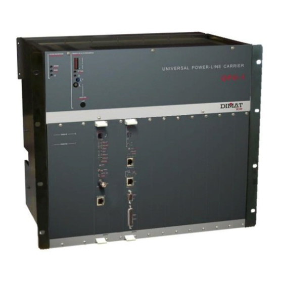
- Page 1 Carrer de les Ciències, 149-151 08908 L’Hospitalet de Llobregat Barcelona-Spain ziv@zivautomation.com www.zivautomation.com Tel.: +34 933 490 700 Fax: +34 933 492 258 UNIVERSAL POWER-LINE CARRIER SYSTEM TYPE OPU-1 GENERAL DESCRIPTION Rev 7 - May 2019 Making the Smart Grid Real 1/67...
- Page 2 NOTE: Information or important aspects to take into account in a procedure, operation or alike. 2/67 UNIVERSAL POWER-LINE CARRIER SYSTEM TYPE OPU-1 GENERAL DESCRIPTION - Rev 7 (May 2019)
-
Page 3: Table Of Contents
2.5.3 Asynchronous programmable modem type MFPU 2.5.4 Others PARTICULARITIES OF THE SYSTEM USE OF THE ANALOG BASE BAND USE OF THE PILOT (ANALOG CHANNEL) MODULATIONS AND DEMODULATIONS LINK SYNCHRONIZATION 3/67 UNIVERSAL POWER-LINE CARRIER SYSTEM TYPE OPU-1 GENERAL DESCRIPTION - Rev 7 (May 2019) - Page 4 USER INTERFACES OPTIONAL BUILT-IN MULTIPLEXER CHARACTERISTICS 5.6.1 MXPU internal multiplexer 5.6.2 DMPU/TMPU internal multiplexer OTHER CHARACTERISTICS OPERATING CONDITIONS MECHANICAL CHARACTERISTICS 5.10 MANAGEMENT SYSTEM APPENDIX A IP ADDRESSING 4/67 UNIVERSAL POWER-LINE CARRIER SYSTEM TYPE OPU-1 GENERAL DESCRIPTION - Rev 7 (May 2019)
-
Page 5: Introduction
It can be configured to transmit analog, digital or both analog and digital channels simultaneously, including teleprotection. When working with analog channels, the OPU-1 terminal can transmit one or two 4 kHz standard channels in each direction. The effective band of each channel, from 300 Hz to 3850 Hz, can be used for the transmission of data at high speed, various VF telegraph channels, teleprotection signals or for a speech-plus service. - Page 6 16 kHz. At 20.25 kbit/s, the transmission and reception channels, each of 4 kHz, can be adjacent, resulting in a total bandwidth of 8 kHz. When working with a QAM digital channel, the OPU-1 can integrate teleprotection signals in the digital operation band.
- Page 7 OPU-1 FIGURE 1 OPU-1 general architecture for 20, 40 and 80 W NOTE: The OPU-1 can work with different line filters, depending on the backplane type. 7/67 UNIVERSAL POWER-LINE CARRIER SYSTEM TYPE OPU-1 GENERAL DESCRIPTION - Rev 7 (May 2019)
- Page 8 OPU-1 FIGURE 2 OPU-1 general architecture for 20 and 40 W with additional filters NOTE: The OPU-1 can work with different line filters, depending on the backplane type. 8/67 UNIVERSAL POWER-LINE CARRIER SYSTEM TYPE OPU-1 GENERAL DESCRIPTION - Rev 7 (May 2019)
-
Page 9: Main Features
In order to establish the date and time the alarms and/or events are produced, the OPU-1 terminal has a real time clock, which can be synchronized with the GPS system or by means of the SNTP protocol. - Page 10 On the front plate of the terminal it is available an Ethernet user interface which is of utility when using the OPU-1 for the interconnection of different line segments. In this case, the built-in Ethernet bridge selects the frames to be transmitted to the remote end, thus making a more efficient use of the communications channel.
-
Page 11: Management System
IP network. The user can access the home web page of the Management System by entering the IP address of the web server of the OPU-1 terminal, once authorisation is gained by means of the user password. -
Page 12: Examples Of Application
OPU-1 EXAMPLES OF APPLICATION The modularity of the OPU-1, together with its wide range of interfaces, permit most configurations found in different applications to be covered. The following examples clearly show some of the most relevant. General purpose Analog channel intended for teleprotection signals, and QAM/OFDM signal for data and speech channels. - Page 13 Different frequency slots in the same high-voltage line (see FIGURE 6) or, even, in different lines (see FIGURE 5). For this application it is necessary the additional filters. FIGURE 6 Frequency congestion solution 13/67 UNIVERSAL POWER-LINE CARRIER SYSTEM TYPE OPU-1 GENERAL DESCRIPTION - Rev 7 (May 2019)
- Page 14 Teleprotection between 3 sites using only three OPU-1 terminals This application consists in sending the same teleprotection information to two different sites using only three OPU-1 terminals equipped each with two sets of 4-command teleprotection system. For this application, additional filters are necessary.
- Page 15 Teleprotection integrated in the digital band The digital operation band is used for the QAM signal and teleprotection signals. For this application the OPU-1 terminal is equipped with a specific set of 4-command teleprotection system. The guard signal is sent to the high-voltage line together with the QAM signal. When the receiver detects the absence of the guard signal, the QAM signal is blocked, for a pre-set period of time, to allow command signal detection.
-
Page 16: Module Description
OPU-1 MODULE DESCRIPTION The OPU-1 terminal can have an output power of 20 W, 40 W and 80 W (PEP), measured at the coaxial-connector output, shared between the analog and digital channels. The OPU-1 basic terminal consists of one shelf of 3 s.u. in height, which contains the power stage modules for 20 W and 40 W, and one shelf of 6 s.u. - Page 17 80 W output power. The module arrangement for 80 W is shown in FIGURE 10. FIGURE 10 OPU-1 module arrangement for 80 W 17/67 UNIVERSAL POWER-LINE CARRIER SYSTEM TYPE OPU-1 GENERAL DESCRIPTION - Rev 7 (May 2019)
- Page 18 The use of additional filters in a twin-channel analog terminal also allows the transmission and reception bands of each channel to be non-adjacent. FIGURE 11 OPU-1 module arrangement for 20 and 40 W with additional filters 18/67 UNIVERSAL POWER-LINE CARRIER SYSTEM TYPE OPU-1...
-
Page 19: Basic Modules For Terminals Of 20 And 40 W
Input voltage of 110 V FAPU.10/20 Input voltage from 110 to 220 V and V If power-supply redundance is necessary, the OPU-1 terminal must be equipped with two power-supply modules. The power supply is protected against polarity inversion. MOPU.1X MANAGEMENT & ANALOG SIGNAL PROCESSING UNIT... - Page 20 This module comprises the receive-channel filter. This module is located in the 3 s.u. shelf. HIPU HF HYBRID This module contains the high-frequency hybrid. This module is located in the 3 s.u. shelf. 20/67 UNIVERSAL POWER-LINE CARRIER SYSTEM TYPE OPU-1 GENERAL DESCRIPTION - Rev 7 (May 2019)
- Page 21 The bandwidth of the line filter may be 8, 16 or 24 kHz. WPPU.01 The bandwidth of the line filter may be 8, 16 or 32 kHz. 21/67 UNIVERSAL POWER-LINE CARRIER SYSTEM TYPE OPU-1 GENERAL DESCRIPTION - Rev 7 (May 2019)
-
Page 22: Additional Modules For 80 W
AMPU.00 For line filter with bandwidth of 8, 16 or 24 kHz. AMPU.02 For line filter with bandwidth of 8, 16 or 32 kHz. 22/67 UNIVERSAL POWER-LINE CARRIER SYSTEM TYPE OPU-1 GENERAL DESCRIPTION - Rev 7 (May 2019) -
Page 23: Optional Internal Multiplexer
2.4.1 MXPU internal multiplexer This optional internal multiplexer of the OPU-1 terminal consists of up to three MULTIPLEXER modules (MXPU). Each MXPU module can house up to three ports. The characteristics of a port depends on the type of submodule installed. - Page 24 7200 bit/s in accordance with Recommendations V.21, V.27ter and V.29 of the ITU-T, as well as modem signals at 2400 bit/s and 1200 bit/s in accordance with Recommendation V.22bis. 24/67 UNIVERSAL POWER-LINE CARRIER SYSTEM TYPE OPU-1 GENERAL DESCRIPTION - Rev 7 (May 2019)
-
Page 25: Dmpu/Tmpu Internal Multiplexer
OPU-1 2.4.2 DMPU/TMPU internal multiplexer This optional internal multiplexer of the OPU-1 terminal consists of up to three modules type DMPU and/or TMPU. The characteristics of the DMPU and TMPU modules are described in the following. DMPU.## Data module. Each DMPU module can house up to six data ports. - Page 26 1 speech communication channel (Port 4/10/16) plus 1 data channel (Port 3/9/15). TMPU.21 2 speech communication channels (Port 4/10/16 and Port 5/11/17) plus 1 data channel (Port 3/9/15). 26/67 UNIVERSAL POWER-LINE CARRIER SYSTEM TYPE OPU-1 GENERAL DESCRIPTION - Rev 7 (May 2019)
-
Page 27: Analog Optional Modules
OPU-1 ANALOG OPTIONAL MODULES When working with analog channels, the OPU-1 terminal can contain up to five optional modules. The following sections detail the large variety of options available. 2.5.1 Speech module For a speech-plus service (T-type channel), the OPU-1 terminal must have a speech module. -
Page 28: Teleprotection Terminals
This module contains the Digital Signal Processor (DSP), which generates the guard and command tones and implements a bank of filters for the reception of commands. 28/67 UNIVERSAL POWER-LINE CARRIER SYSTEM TYPE OPU-1 GENERAL DESCRIPTION - Rev 7 (May 2019) -
Page 29: Teleprotection Terminal Using Fsk Channels
The analog teleprotection terminal using dual tone is able to transmit and receive up to four independent commands and in any combination in a 1 kHz, 2 kHz or 4 kHz analog band. The terminal is constituted by a single module. 29/67 UNIVERSAL POWER-LINE CARRIER SYSTEM TYPE OPU-1 GENERAL DESCRIPTION - Rev 7 (May 2019) -
Page 30: Teleprotection Terminal Integrated In The Digital Band
2.5.2.4 Teleprotection terminal integrated in the digital band When only working with a QAM digital channel (of 8 kHz or 16 kHz), the OPU-1 terminal can be equipped with a specific analog teleprotection terminal using single tone or dual tone that will be able to use the digital operation band to transmit teleprotection signals. - Page 31 It contains four command input and output circuits together with two relays for signalling and/or alarm, configurable by the user. 31/67 UNIVERSAL POWER-LINE CARRIER SYSTEM TYPE OPU-1 GENERAL DESCRIPTION - Rev 7 (May 2019)
-
Page 32: Asynchronous Programmable Modem Type Mfpu
Audio-frequency signal filter and amplifier with phase equalizer. It is used to select a determinate band and to carry out the transit towards other communication channels. It includes a transformer-decoupled output with programmable level. 32/67 UNIVERSAL POWER-LINE CARRIER SYSTEM TYPE OPU-1 GENERAL DESCRIPTION - Rev 7 (May 2019) - Page 33 As it is not possible to connect the AF reception and transmission buses of the OPU-1 terminal to each other, the combination of six inputs and six outputs is not permitted.
-
Page 34: Particularities Of The System
The pilot is situated below the available band, at the virtual frequency of 150 Hz, which makes all of the band between 300 Hz and 3850 Hz available for the transmission of information. 34/67 UNIVERSAL POWER-LINE CARRIER SYSTEM TYPE OPU-1 GENERAL DESCRIPTION - Rev 7 (May 2019) - Page 35 The value thus determined is compared with pre-set thresholds in order to block the previously-programmed audio-frequency outputs and to deliver an excess-noise alarm. 35/67 UNIVERSAL POWER-LINE CARRIER SYSTEM TYPE OPU-1 GENERAL DESCRIPTION - Rev 7 (May 2019)
-
Page 36: Modulations And Demodulations
The input of the OFDM/OQAM modulator is a complex symbol stream for each of the carriers of the system. 36/67 UNIVERSAL POWER-LINE CARRIER SYSTEM TYPE OPU-1 GENERAL DESCRIPTION - Rev 7 (May 2019) -
Page 37: Link Synchronization
In order to establish the date and time the alarms and/or events are produced, the OPU-1 terminal has a real time clock, which can be synchronized with the GPS system or by means of the SNTP protocol. -
Page 38: Gps Synchronization
GPS system. In order to do so, the time, day, month and year must be programmed in the OPU-1 terminal and it must then be connected to a GPS receiver that has a timing output, which must be an IRIG-B output. The IRIG-B standard establishes the format of signals used to identify specific instants of time. -
Page 39: Main Management Menus
OPU-1 MAIN MANAGEMENT MENUS The home web page of the OPU-1 Management System is as shown in FIGURE 12. As can be seen, four main menus appear. The first menu, System, controls the flow of information entering and leaving the Management System, allows the pages necessary for... -
Page 40: System Menu
It also allows alarms to be assigned to the external signalling relays. ❖ Terminal configuration In the OPU-1 terminals it is possible to program a numeric identification and a description of up to 50 characters. Before programming the operating parameters it is necessary to configure the terminal. - Page 41 It also makes it possible to de-activate the service associated to a port, activating it again when necessary. 41/67 UNIVERSAL POWER-LINE CARRIER SYSTEM TYPE OPU-1 GENERAL DESCRIPTION - Rev 7 (May 2019)
-
Page 42: Monitoring Menu
• Low RCV level in digital channel. • RCV level exceeded in digital channel. • Failure in G.703 interface input in digital channel. 42/67 UNIVERSAL POWER-LINE CARRIER SYSTEM TYPE OPU-1 GENERAL DESCRIPTION - Rev 7 (May 2019) -
Page 43: Alignment Help Menu
This option allows a reset of the equipment to be carried out without having to use the button on the front, block the Automatic Gain Control (AGC) circuit, and cancel the phase amplitude equalizer (analog channel). 43/67 UNIVERSAL POWER-LINE CARRIER SYSTEM TYPE OPU-1 GENERAL DESCRIPTION - Rev 7 (May 2019) - Page 44 This adjustment is carried out by means of a signal generated by the OPU-1 terminal's own transmitter. Control of audio-frequency loops (analog channel) To control the state of a communication system it is necessary to know the response curve of each link.
-
Page 45: Technical Characteristics
If desired, the OPU-1 can function as a High-Frequency teleprotection system. This functionality enables electrical power utilities to transmit teleprotection commands over high-voltage lines, in only one standard 4 kHz channel, using 2 kHz for Tx and 2 kHz for Rx. - Page 46 The possibilities can be enlarged with the use of the additional filters FIGURE 13 Transmission capacity examples NOTE: The OPU-1 can work with different line filters, depending on the backplane type. 46/67 UNIVERSAL POWER-LINE CARRIER SYSTEM TYPE OPU-1 GENERAL DESCRIPTION - Rev 7 (May 2019)
- Page 47 20 dB input level variations cause variations Efficiency of less than 0.2 dB at the output Automatic Gain Control (AGC) 47 dB range in digital channel 47/67 UNIVERSAL POWER-LINE CARRIER SYSTEM TYPE OPU-1 GENERAL DESCRIPTION - Rev 7 (May 2019)
-
Page 48: High-Frequency Characteristics
➢ Analog channel: higher than 65 dB at Receiver selectivity 300 Hz, and higher than 75 dB starting from 4 kHz; in accordance with IEC 495 cls. 5.3.1.5. 48/67 UNIVERSAL POWER-LINE CARRIER SYSTEM TYPE OPU-1 GENERAL DESCRIPTION - Rev 7 (May 2019) -
Page 49: Qam Digital Modem Characteristics
➢ Medium: 40.5 kbit/s. ➢ Lower: 27 kbit/s. The terminal permanently measures the S/N ratio in the digital band to decide the speed increase before retraining (1.5 s). 49/67 UNIVERSAL POWER-LINE CARRIER SYSTEM TYPE OPU-1 GENERAL DESCRIPTION - Rev 7 (May 2019) -
Page 50: Ofdm Digital Modem Characteristics
(OFDM/OQAM) Fall back/increase rate Automatic 32 kHz bandwidth 324 kbit/s 16 kHz bandwidth 160 kbit/s 8 kHz bandwidth 72 kbit/s 4 kHz bandwidth 32 kbit/s 50/67 UNIVERSAL POWER-LINE CARRIER SYSTEM TYPE OPU-1 GENERAL DESCRIPTION - Rev 7 (May 2019) -
Page 51: User Interfaces
10% and 100% in the command signal Boosting control By means of optocoupler. Input voltage between 30 V and 150 V 51/67 UNIVERSAL POWER-LINE CARRIER SYSTEM TYPE OPU-1 GENERAL DESCRIPTION - Rev 7 (May 2019) -
Page 52: Optional Built-In Multiplexer Characteristics
3 fax signals up to 7200 bit/s in accordance with Recommendations V.21, V.27ter and V.29 of the ITU-T; modem signals at 2400 and 1200 bit/s in accordance with Recommendation V.22bis of the ITU-T 52/67 UNIVERSAL POWER-LINE CARRIER SYSTEM TYPE OPU-1 GENERAL DESCRIPTION - Rev 7 (May 2019) -
Page 53: Dmpu/Tmpu Internal Multiplexer
TMPU.21: two speech ports plus one data port Drop-insert functionality in DMPU module data ports. The drop-insert is particularly suitable for half-duplex communications or polling systems (Central Unit/Remotes 53/67 UNIVERSAL POWER-LINE CARRIER SYSTEM TYPE OPU-1 GENERAL DESCRIPTION - Rev 7 (May 2019) - Page 54 ❖ V.24 asynchronous ❖ RS-422 of the ITU-T ❖ RS-485 (HD/FD) Implementation enhanced V.14 asynchronous mode (allows communication between equipment at speeds of up to 10% difference) 54/67 UNIVERSAL POWER-LINE CARRIER SYSTEM TYPE OPU-1 GENERAL DESCRIPTION - Rev 7 (May 2019)
-
Page 55: Other Characteristics
➢ 2 or 4-command teleprotection system using single tone in a 4 kHz bandwidth. ➢ 2 or 4-command teleprotection system using FSK channels in a 4 kHz bandwidth. 55/67 UNIVERSAL POWER-LINE CARRIER SYSTEM TYPE OPU-1 GENERAL DESCRIPTION - Rev 7 (May 2019) - Page 56 Loss of synchronism, Pilot loss, Low Signal/Noise ratio, AF limiter operation, Temperature alarm, Terminal configuration error, Hardware failure, BER alarm, Excess or low receive level and Failure in G.703 interface input. 56/67 UNIVERSAL POWER-LINE CARRIER SYSTEM TYPE OPU-1 GENERAL DESCRIPTION - Rev 7 (May 2019)
- Page 57 ❖ Data loop in local and remote terminals. ❖ High-frequency loop (isolated terminal). ❖ Displaying of the XMT and RCV signal space constellation means oscilloscope (QAM). 57/67 UNIVERSAL POWER-LINE CARRIER SYSTEM TYPE OPU-1 GENERAL DESCRIPTION - Rev 7 (May 2019)
-
Page 58: Operating Conditions
95%, in accordance with IEC 721-3-3 class 3K5 (climatogram 3K5) +55 C for a period no longer than 24 hours Maximum temperature (IEC 495 cls 3.1) 58/67 UNIVERSAL POWER-LINE CARRIER SYSTEM TYPE OPU-1 GENERAL DESCRIPTION - Rev 7 (May 2019) -
Page 59: Mechanical Characteristics
20 kg (20/40 W terminal) 23 kg (20/40 W terminal with options) 30 kg (80 W terminal) 33 kg (80 W terminal with options) Module arrangement See FIGURE 15 59/67 UNIVERSAL POWER-LINE CARRIER SYSTEM TYPE OPU-1 GENERAL DESCRIPTION - Rev 7 (May 2019) - Page 60 Terminals that do not have disconnect devices and that are suitable for flexible conductors of up to 2.5 mm of section or rigid conductors of up to 2.5 mm of section 60/67 UNIVERSAL POWER-LINE CARRIER SYSTEM TYPE OPU-1 GENERAL DESCRIPTION - Rev 7 (May 2019)
-
Page 61: Management System
❖ Monitoring: Chronological list of alarms and events, terminal alarms, receive pilot level, S/N ratio, Quality of the link (established with regard to Recommendation G.821), and state of the digital ports. 61/67 UNIVERSAL POWER-LINE CARRIER SYSTEM TYPE OPU-1 GENERAL DESCRIPTION - Rev 7 (May 2019) - Page 62 SET operation. Supervision by means of SNMP agent Possible from an SNMP application. The most of the variables of the OPU-1 that can be monitored are to be found in the MIB of the terminal, which can be integrated into the management platform.
- Page 63 Microsoft Windows XP Service Pack 2 version, Microsoft Windows 7 or Microsoft Windows 10 Web browser Microsoft Internet Explorer v 6.0 or higher JAVA virtual machine Version 1.7 and higher (Sun Microsystems) 63/67 UNIVERSAL POWER-LINE CARRIER SYSTEM TYPE OPU-1 GENERAL DESCRIPTION - Rev 7 (May 2019)
-
Page 64: Ip Addressing
OPU-1 APPENDIX A IP ADDRESSING 64/67 UNIVERSAL POWER-LINE CARRIER SYSTEM TYPE OPU-1 GENERAL DESCRIPTION - Rev 7 (May 2019) - Page 65 The Management System of the OPU-1 terminals is based on web technology. This technology is based on a Client/Server model in which the Server (OPU-1 terminal) replies to requests made by the Client (web browser of the management computer) with data that it has stored.
- Page 66 IP address that corresponds to the network is determined, and also the part that corresponds to the host, as shown in FIGURE 18. FIGURE 18 IP address and subnet mask 66/67 UNIVERSAL POWER-LINE CARRIER SYSTEM TYPE OPU-1 GENERAL DESCRIPTION - Rev 7 (May 2019)
- Page 67 If the OPU-1 terminal and the computer are connected directly or through a LAN (they belong to the same network), the IP address of each of them must have the same network number and a different host number, so the subnet mask must be the same for both.
Need help?
Do you have a question about the OPU-1 and is the answer not in the manual?
Questions and answers