Table of Contents
Advertisement
Quick Links
Communication solutions for power utilities
UNIVERSAL TELEPROTECTION
TPU-1
INSTALLATION AND COMMISSIONING MANUAL
Web version TPU-1R
Rev. 5.9 - May 2018
DIMAT
Antonio Machado,78-80 08840
Viladecans, Barcelona-Spain
Tel.: +34 933 490 700
Fax: +34 933 492 258
Mail to: ziv@zivautomation.com
www.zivautomation.com
1/69
Advertisement
Table of Contents

Related Manuals for DIMAT TPU-1

Summary of Contents for DIMAT TPU-1
- Page 1 Communication solutions for power utilities UNIVERSAL TELEPROTECTION TPU-1 INSTALLATION AND COMMISSIONING MANUAL Web version TPU-1R Rev. 5.9 - May 2018 DIMAT Antonio Machado,78-80 08840 Viladecans, Barcelona-Spain Tel.: +34 933 490 700 Fax: +34 933 492 258 Mail to: ziv@zivautomation.com www.zivautomation.com...
-
Page 2: Web Version Tpu-1R
NOTE: Information or important aspects to take into account in a procedure, operation or alike. 2/69 UNIVERSAL TELEPROTECTION TPU-1 INSTALLATION AND COMMISSIONING MANUAL Web version TPU-1R - Rev. 5.9 (May 2018) -
Page 3: Table Of Contents
4.3.6 IATU and IBTU modules PROTECTION-SIDE INTERFACE MODULE (CIRCUITS FROM ONE TO TWO COMMANDS) GOOSE PROTECTION INTERFACE MODULE RELAY INTERFACE MODULES MODULES FOR TELESIGNALLING AND REMOTE MEASUREMENTS 32 3/69 UNIVERSAL TELEPROTECTION TPU-1 INSTALLATION AND COMMISSIONING MANUAL Web version TPU-1R - Rev. 5.9 (May 2018) - Page 4 TRANSPORT AND STORAGE TRANSPORT STORAGE APPENDIX A IP ADDRESSING APPENDIX B IEC 61850 STANDARD APPENDIX C CABINET-MOUNTING TERMINAL BLOCKS APPENDIX D OPTIONAL LCD DISPLAY 4/69 UNIVERSAL TELEPROTECTION TPU-1 INSTALLATION AND COMMISSIONING MANUAL Web version TPU-1R - Rev. 5.9 (May 2018)
-
Page 5: Introduction
Communication solutions for power utilities INTRODUCTION This manual describes the installation and commissioning procedure for the TPU-1 universal teleprotection terminal. Firstly, it indicates the mechanical characteristics of the terminal and how to replace the modules without damaging either the modules or the terminal. It goes on to describe the function of the optical indicators on the front plate and shows the position and function of the internal jumpers that can be configured by the user. -
Page 6: Mechanical Characteristics
Communication solutions for power utilities MECHANICAL CHARACTERISTICS The TPU-1 terminal is made up of a 19” shelf that is 3 standard units (s.u.) in height, prepared for rack mounting. Figure 1 shows the general dimensions of the shelf as well as the position of the fastening holes. -
Page 7: Shelf Module Capacity
Figure 2. Figure 2 Internal rear view of the TPU-1 shelf The correspondence between connectors and slots should be taken into account when establishing the constitution of the equipment, from the Management System, in order to carry out configuration. -
Page 8: Replacing The Modules
Once the module is inserted in the shelf, tighten the module to the chassis and, if necessary, attach the earth cable to the upper screw. 8/69 UNIVERSAL TELEPROTECTION TPU-1 INSTALLATION AND COMMISSIONING MANUAL Web version TPU-1R - Rev. 5.9 (May 2018) -
Page 9: Front Plate Elements
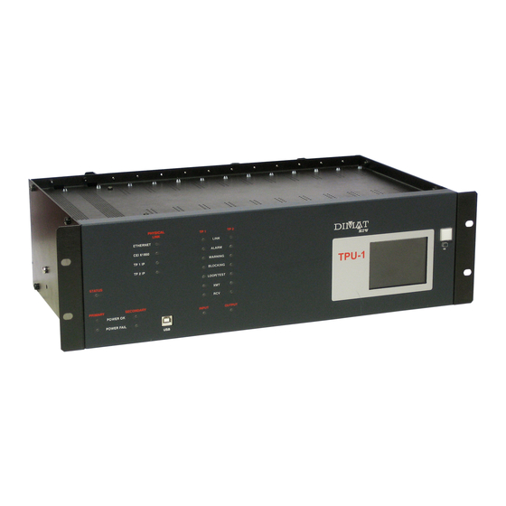
Communication solutions for power utilities FRONT PLATE ELEMENTS The TPU-1 terminal has twenty-five LEDs on the front plate. The LEDs identified as PRIMARY and SECONDARY are associated with the terminal power supply. The PHYSICAL LINK LEDs indicate the interface type being active, and the LEDs identified as TP 1 and TP2 are associated with the two possible communication channels that can manage the terminal and to the command transmission and reception circuits. -
Page 10: Web Version Tpu-1R
Communication solutions for power utilities Figure 4 Signalling of LEDs (II) Figure 5 Optional LCD display 10/69 UNIVERSAL TELEPROTECTION TPU-1 INSTALLATION AND COMMISSIONING MANUAL Web version TPU-1R - Rev. 5.9 (May 2018) -
Page 11: Internal Settings
1 of J7 and pin 1 of J8 is carried out Figure 6 Location of the configuration elements of the MWTU module The IP address in factory is the 172.16.6.3 11/69 UNIVERSAL TELEPROTECTION TPU-1 INSTALLATION AND COMMISSIONING MANUAL Web version TPU-1R - Rev. 5.9 (May 2018) -
Page 12: Protection-Side Interface Modules (Circuits From One To Two Commands)
24 V , 58 V for 48 V , 132 V for 110 V and 264 V for 220 V a) Model A 12/69 UNIVERSAL TELEPROTECTION TPU-1 INSTALLATION AND COMMISSIONING MANUAL Web version TPU-1R - Rev. 5.9 (May 2018) -
Page 13: Web Version Tpu-1R
Communication solutions for power utilities b) Model B Figure 7 Input-activation nominal-voltage configuration jumpers of the IPTU module 13/69 UNIVERSAL TELEPROTECTION TPU-1 INSTALLATION AND COMMISSIONING MANUAL Web version TPU-1R - Rev. 5.9 (May 2018) -
Page 14: Digital Line Interface Module
- P1:1 and P2:1 open: 75 Ω (BNC). In IDTU.00 modules of version 3.1, the type of connector (BNC or RJ-45) is programmed from the TPU-1 Management System. The solder jumpers C97 and C98 determine whether the cable shield is connected to earth or not: - C97 and C98 open: Balanced (cable shield NOT connected to earth). -
Page 15: Web Version Tpu-1R
Communication solutions for power utilities Figure 8 Location of jumpers S7 and S8, prepared for soldering, of the IDTU.00 module of version lower than 3.0 15/69 UNIVERSAL TELEPROTECTION TPU-1 INSTALLATION AND COMMISSIONING MANUAL Web version TPU-1R - Rev. 5.9 (May 2018) -
Page 16: Web Version Tpu-1R
Location of P1-P2 setting b) Location of C97 and C98 solder jumpers Figure 9 Location of settings in the IDTU.00 module of version 3.0 16/69 UNIVERSAL TELEPROTECTION TPU-1 INSTALLATION AND COMMISSIONING MANUAL Web version TPU-1R - Rev. 5.9 (May 2018) -
Page 17: Digital Signal I/O Interface Module (Dstu)
Figure 10 shows the position of the input-activation nominal-voltage configuration jumpers in the DSTU module. Figure 10 Input-activation nominal-voltage configuration jumpers of the DSTU module 17/69 UNIVERSAL TELEPROTECTION TPU-1 INSTALLATION AND COMMISSIONING MANUAL Web version TPU-1R - Rev. 5.9 (May 2018) -
Page 18: Connections
Appendix C. Figure 11 Rear view of the TPU-1 shelf In disturbed environments, it is recommended to use screened cables for the connections. For safety reasons the screen of the connection cables must be grounded, the connection to earth being made at just one end to avoid interference. -
Page 19: Power Supply
LED POWER FAIL on the front plate light up but the N.C. and C contacts of the alarm relay are also short-circuited. Figure 12 ATPU power-supply module 19/69 UNIVERSAL TELEPROTECTION TPU-1 INSTALLATION AND COMMISSIONING MANUAL Web version TPU-1R - Rev. 5.9 (May 2018) -
Page 20: Processing Module
GPS synchronized time equipment. The BNC connector allows the TPU-1 terminal to synchronize its internal real time clock with the time reference given by any GPS synchronized time equipment that has an IRIG-B standard output. -
Page 21: Line Interface Modules
Communication solutions for power utilities LINE INTERFACE MODULES The TPU-1 terminal has one or two line interface modules, depending on whether it manages one or two communication channels. The line interface modules are divided into analog and digital line interface modules. -
Page 22: Web Version Tpu-1R
Use of the connector of the IETU module for X.21 interface Figure 16 Use of the connector of the IETU module for V.35 interface 22/69 UNIVERSAL TELEPROTECTION TPU-1 INSTALLATION AND COMMISSIONING MANUAL Web version TPU-1R - Rev. 5.9 (May 2018) -
Page 23: Web Version Tpu-1R
Figure 18 Use of the connector of the IETU module for G.703 contradirectional interface Make sure that the module is completely fixed to the chassis. 23/69 UNIVERSAL TELEPROTECTION TPU-1 INSTALLATION AND COMMISSIONING MANUAL Web version TPU-1R - Rev. 5.9 (May 2018) -
Page 24: Idtu Module
(output not balanced) or not (output balanced) is configured by internal settings. In IDTU.00 modules of version 3.1, the type of connector (BNC or RJ-45) is programmed from the TPU-1 Management System. Make sure that the module is completely fixed to the chassis. LEDs associated with the RJ-45 connector •... -
Page 25: Iotu Module
FC connectors, one for transmission and the other for reception. Make sure that the module is completely fixed to the chassis. Figure 20 IOTU line interface module connectors 25/69 UNIVERSAL TELEPROTECTION TPU-1 INSTALLATION AND COMMISSIONING MANUAL Web version TPU-1R - Rev. 5.9 (May 2018) -
Page 26: Ioct Module
Make sure that the module is completely fixed to the chassis. a) IOCT module with ST female connectors b) IOCT module with FC female connectors (IOCT.00) (IOCT.01) Figure 21 IOCT line interface module connectors 26/69 UNIVERSAL TELEPROTECTION TPU-1 INSTALLATION AND COMMISSIONING MANUAL Web version TPU-1R - Rev. 5.9 (May 2018) -
Page 27: Ipit Module
Make sure that the module is completely fixed to the chassis. c) IPIT module with electrical connectors d) IPIT module with optical fiber connectors (IPIT.01) (IPIT.00) Figure 22 IP communications interface module (IPIT) connectors 27/69 UNIVERSAL TELEPROTECTION TPU-1 INSTALLATION AND COMMISSIONING MANUAL Web version TPU-1R - Rev. 5.9 (May 2018) -
Page 28: Iatu And Ibtu Modules
(analog), Low Signal/Noise ratio (analog), Signal loss (analog), Low guard-signal level/Excess guard-signal level (analog), MTD alarm (IP interface), CDV alarm (IP interface), CLR alarm (IP interface), IP link failure (IP interface). 28/69 UNIVERSAL TELEPROTECTION TPU-1 INSTALLATION AND COMMISSIONING MANUAL Web version TPU-1R - Rev. 5.9 (May 2018) -
Page 29: Protection-Side Interface Module (Circuits From One To Two Commands)
The earth connection of the cable must be connected to the upper fixing screw. Make sure that the module is completely fixed to the chassis. 29/69 UNIVERSAL TELEPROTECTION TPU-1 INSTALLATION AND COMMISSIONING MANUAL Web version TPU-1R - Rev. 5.9 (May 2018) -
Page 30: Goose Protection Interface Module
Communication solutions for power utilities GOOSE PROTECTION INTERFACE MODULE The GOOSE protection interface module (IEPT) allows the TPU-1 terminal to communicate with the protection terminals according to IEC 61850 standard. Figure 25 shows a front view of the IEPT module. As can be seen in the figure, the module has two ports type 10/100Base-Tx with RJ-45 connector (IEPT.01). -
Page 31: Relay Interface Modules
The earth connection of the cable must be connected to the upper fixing screw. Make sure that the module is completely fixed to the chassis. 31/69 UNIVERSAL TELEPROTECTION TPU-1 INSTALLATION AND COMMISSIONING MANUAL Web version TPU-1R - Rev. 5.9 (May 2018) -
Page 32: Modules For Telesignalling And Remote Measurements
Communication solutions for power utilities MODULES FOR TELESIGNALLING AND REMOTE MEASUREMENTS The TPU-1 terminal, when equipped with current measuring and digital signal I/O interface modules, can transmit and receive analog measurements and digital signals. Figure 27 shows a front view of an MCTU module, and Figure 28 a front view of a DSTU module. -
Page 33: Installation And Commissioning Manual Web Version Tpu-1R - Rev. 5.9 (May
Communication solutions for power utilities DI: Digital inputs (remote measurements) DO: Digital outputs (remote measurements) Connector of the digital signal module (DSTU) Figure 28 33/69 UNIVERSAL TELEPROTECTION TPU-1 INSTALLATION AND COMMISSIONING MANUAL Web version TPU-1R - Rev. 5.9 (May 2018) -
Page 34: Commissioning Procedure
The modules contain components sensitive to static electricity, so great care must be taken when handling them. It is advisable to use an antistatic wristband connected to earth. 34/69 UNIVERSAL TELEPROTECTION TPU-1 INSTALLATION AND COMMISSIONING MANUAL Web version TPU-1R - Rev. 5.9 (May 2018) -
Page 35: Starting Up The Terminal
CONFIGURATION OF THE WEB SERVER The network configuration of the web server can be modified, if the terminal has already been accessed, from the option Network parameters of the Server submenu of the TPU-1 Management System Equipment menu. From the said option, it is possible to modify parameters such as IP address, subnet mask, etc., in order for them to be compatible with the computer or computers that are going to be... -
Page 36: Characteristics Of The Management Computer
Connections 10/100Base-TX LAN interface The TPU-1 terminal can have a 10/100Base-TX LAN interface, which allows it to be integrated into any network (LAN) that uses this interface. The connector is on the front of the MWTU module and is a female 8-pin RJ-45. -
Page 37: Web Version Tpu-1R
Unshielded twisted pair category five cable (UTP-5) with RJ-45 connector according to ANSI/TIA/EIA-568-A standard If the TPU-1 terminal is connected directly to the computer, a crossover cable must be used, see Figure 30, where pairs 2 and 3 at one end of the cable are reversed at the other. -
Page 38: Web Version Tpu-1R
Straight-through cable 100Base-FX LAN interface Instead of the previous interface, the TPU-1 terminal can have a 100Base-FX LAN interface that allows advantage to be taken of the characteristics of bandwidth, noise immunity, low attenuation, long range, etc. given by the optical fiber. The connector is on the front of the MWTU module and is a MT-RJ. -
Page 39: Configuration
If the Web Management is performed from an IP network and it is necessary to use networking devices such as hubs, switches, routers, etc. it is assumed that the user has such elements and is capable of configuring them to integrate the TPU-1 terminal in their work group. -
Page 40: Starting Up The Web Server
My computer option in the Security section and select it. Once previous operations have been carried out, in the ADDRESS field of the browser field key the IP address of the web server of the TPU-1 terminal. The IP address in factory is the 172.16.6.3. -
Page 41: Web Version Tpu-1R
Figure 33 Access control page Access to the Web Management from the TPU-1 terminals requires a user password, which comprises a user identification and a password. If the user identification or password are not introduced correctly, the system asks for the user password again, up to two times. -
Page 42: Certificate Of Authenticity
(ZIVCommunications.cer). If this file is not executed it is not possible to access the TPU-1 Management System. This step can be avoided subsequently by marking the "Always trust contents from this publisher"... -
Page 43: Updating The Web Server
Monitoring of the terminal. To be able to perform off-line management, it is necessary for the management computer to have been previously connected to the TPU-1 terminal to obtain the pages corresponding to the management from the server. -
Page 44: Maintenance
Management System, it may be verified that the command-output contacts associated with the command are closed. Then, repeat the verification process for the command-input circuits of the remote terminal. 44/69 UNIVERSAL TELEPROTECTION TPU-1 INSTALLATION AND COMMISSIONING MANUAL Web version TPU-1R - Rev. 5.9 (May 2018) -
Page 45: Web Version Tpu-1R
One way of energizing the relays is to program the blocking option of the Alignment menu of the Management System, if the programming associated with the relays provides alarm generation under this circumstance. 45/69 UNIVERSAL TELEPROTECTION TPU-1 INSTALLATION AND COMMISSIONING MANUAL Web version TPU-1R - Rev. 5.9 (May 2018) -
Page 46: Web Version Tpu-1R
- Reset the chronological register using the Chronological register option of the Monitoring menu. - Reset the transmitted and received command counters using the Counter reset option of the Alignment menu. 46/69 UNIVERSAL TELEPROTECTION TPU-1 INSTALLATION AND COMMISSIONING MANUAL Web version TPU-1R - Rev. 5.9 (May 2018) -
Page 47: Transport And Storage
TRANSPORT AND STORAGE TRANSPORT When delivered the TPU-1 terminals are packed in wooden boxes prepared for easy transportation. Each wooden box contains one cardboard box. The cardboard box contains the equipment, which is properly packed, together with the possible equipment accessories. -
Page 48: Storage
The user must immediately notify ZIV of any anomaly about the material received and, if applicable, return all material to ZIV in the original package. The TPU-1 terminals should be stored in its own packaging until installation. Storage must be done in premises protected from the weather, Class C according to EN 60870-2-2 standard. -
Page 49: Ip Addressing
The Management System of the TPU-1 terminals is based on web technology. This technology is based on a Client/Server model in which the Server (TPU-1 terminal) replies to requests made by the Client (web browser of the management computer) with data that it has stored. -
Page 50: Web Version Tpu-1R
IP address that corresponds to the network is determined, and also the part that corresponds to the host, as shown in Figure 36. Figure 36 IP address and subnet mask 50/69 UNIVERSAL TELEPROTECTION TPU-1 INSTALLATION AND COMMISSIONING MANUAL Web version TPU-1R - Rev. 5.9 (May 2018) -
Page 51: Web Version Tpu-1R
If the TPU-1 terminal and the computer are connected directly or through a LAN (they belong to the same network), the IP address of each of them must have the same network number and a different host number, so the subnet mask must be the same for both. -
Page 52: Iec 61850 Standard
Ethernet frames, increasing in this way the global capacity of the network at the expense of however a higher complexity and cost. 52/69 UNIVERSAL TELEPROTECTION TPU-1 INSTALLATION AND COMMISSIONING MANUAL Web version TPU-1R - Rev. 5.9 (May 2018) -
Page 53: Web Version Tpu-1R
IED, given that in this environment collisions are somewhat possible. The LAN configurations with switch or hub at 100 Mbit/s are capable of delivering more than 100 messages within the 4 ms permitted. 53/69 UNIVERSAL TELEPROTECTION TPU-1 INSTALLATION AND COMMISSIONING MANUAL Web version TPU-1R - Rev. 5.9 (May 2018) -
Page 54: Cabinet-Mounting Terminal Blocks
Protection-side interface modules (IPTU) determine the number of cabinet-mounting terminal blocks. When the TPU-1 houses from one to four IPTU modules, only one cabinet- mounting terminal block is required and, when there are more than four IPTU modules, two cabinet-mounting terminal blocks are necessary. -
Page 55: Web Version Tpu-1R
2.5 mm flexible conductors and up to 4 mm rigid conductors. Figure 38 shows assignment of these terminals. Figure 38 ZPTU.00 terminal block 55/69 UNIVERSAL TELEPROTECTION TPU-1 INSTALLATION AND COMMISSIONING MANUAL Web version TPU-1R - Rev. 5.9 (May 2018) -
Page 56: Web Version Tpu-1R
A balanced-to-unbalanced adapter is available upon request for connecting a balanced 120 twisted pair interface to this unbalanced 75 coaxial interface and vice versa. 56/69 UNIVERSAL TELEPROTECTION TPU-1 INSTALLATION AND COMMISSIONING MANUAL Web version TPU-1R - Rev. 5.9 (May 2018) -
Page 57: Web Version Tpu-1R
The terminals have disconnect devices and are suitable for up to 2.5 mm flexible conductors and up to 4 mm rigid conductors. Figure 42 shows the assignment of these terminals. Figure 42 ZRTU.## terminal block 57/69 UNIVERSAL TELEPROTECTION TPU-1 INSTALLATION AND COMMISSIONING MANUAL Web version TPU-1R - Rev. 5.9 (May 2018) -
Page 58: Web Version Tpu-1R
4 mm rigid conductors. Figure 43 shows the assignment of the BB1 and BB2 terminals. Figure 43 ZCTU.01 BB1 & BB2 terminal blocks 58/69 UNIVERSAL TELEPROTECTION TPU-1 INSTALLATION AND COMMISSIONING MANUAL Web version TPU-1R - Rev. 5.9 (May 2018) -
Page 59: Web Version Tpu-1R
4 mm rigid conductors. Figure 44 shows the assignment of the BB1 and BB2 terminals. Figure 44 ZSTU.00 BB1 & BB2 terminal blocks 59/69 UNIVERSAL TELEPROTECTION TPU-1 INSTALLATION AND COMMISSIONING MANUAL Web version TPU-1R - Rev. 5.9 (May 2018) -
Page 60: Web Version Tpu-1R
Communication solutions for power utilities Figure 45 Main cabinet-mounting terminal block for two digital channels and four IPTU modules 60/69 UNIVERSAL TELEPROTECTION TPU-1 INSTALLATION AND COMMISSIONING MANUAL Web version TPU-1R - Rev. 5.9 (May 2018) -
Page 61: Web Version Tpu-1R
Communication solutions for power utilities Figure 46 Main cabinet-mounting terminal block for a digital channel and an analog channel (three IPTU modules) 61/69 UNIVERSAL TELEPROTECTION TPU-1 INSTALLATION AND COMMISSIONING MANUAL Web version TPU-1R - Rev. 5.9 (May 2018) -
Page 62: Web Version Tpu-1R
Communication solutions for power utilities Figure 47 Main cabinet-mounting terminal block for two analog channels (three IPTU modules) 62/69 UNIVERSAL TELEPROTECTION TPU-1 INSTALLATION AND COMMISSIONING MANUAL Web version TPU-1R - Rev. 5.9 (May 2018) -
Page 63: Web Version Tpu-1R
Communication solutions for power utilities Figure 48 Main cabinet-mounting terminal block for one analog channel and two relay interface modules (two IPTU modules) 63/69 UNIVERSAL TELEPROTECTION TPU-1 INSTALLATION AND COMMISSIONING MANUAL Web version TPU-1R - Rev. 5.9 (May 2018) -
Page 64: Web Version Tpu-1R
Communication solutions for power utilities Figure 49 Additional cabinet-mounting terminal block (eight IPTU modules) 64/69 UNIVERSAL TELEPROTECTION TPU-1 INSTALLATION AND COMMISSIONING MANUAL Web version TPU-1R - Rev. 5.9 (May 2018) -
Page 65: Web Version Tpu-1R
Communication solutions for power utilities Figure 50 General dimensions of the cabinet-mounting terminal block 65/69 UNIVERSAL TELEPROTECTION TPU-1 INSTALLATION AND COMMISSIONING MANUAL Web version TPU-1R - Rev. 5.9 (May 2018) -
Page 66: Optional Lcd Display
OPTIONAL LCD DISPLAY In order to monitor certain parameters from the front plate of the terminal, without having to access the corresponding option of the Management System, the TPU-1 Universal Teleprotection terminal can be supplied with an LCD display, on demand. -
Page 67: Installation And Commissioning Manual Web Version Tpu-1R - Rev. 5.9 (May
4. Network parameters (IP interface, if be the case). be the case). 5. Terminal alarms (general). 6. Terminal alarms (specific, if be the case). 67/69 UNIVERSAL TELEPROTECTION TPU-1 INSTALLATION AND COMMISSIONING MANUAL Web version TPU-1R - Rev. 5.9 (May 2018) -
Page 68: Web Version Tpu-1R
9. Command transmission counters of 10. Command reception counters of each communication channel. each communication channel. 11. Loop status (without loops). 12. Loop status (with loops). 68/69 UNIVERSAL TELEPROTECTION TPU-1 INSTALLATION AND COMMISSIONING MANUAL Web version TPU-1R - Rev. 5.9 (May 2018) -
Page 69: Web Version Tpu-1R
Figure 52 Blocking signalling in channel Terminal blocking is carried out from the corresponding option of the Management System. When in a blocking situation, the TPU-1 terminal cannot activate any output, whether compatible or not with the IEC 61850 standard. 69/69 UNIVERSAL TELEPROTECTION TPU-1 INSTALLATION AND COMMISSIONING MANUAL Web version TPU-1R - Rev.
Need help?
Do you have a question about the TPU-1 and is the answer not in the manual?
Questions and answers