
Related Manuals for IXO 64A

Summary of Contents for IXO 64A
- Page 1 4A Body frame Circuit board and left Fuel tank fixation , Exhaust duct installation , Wiring fixation , Saloon installation on Chassis , Testing of Dashboard Electric Functions and Steering , Body frame inital preparation .
- Page 2 Lead one by one , through square opening in A Chassis panel the following wires : 63N G Cable ( white-gray ), 63O M Cable ( green- yellow ) , 63P S Cable red-green ) , 61F J Cable ( red-green ) and 49F B Cable ( yellow...
- Page 3 Further , fit the plugs of 61F J Cable ( red-green ) and 49F B Cable ( yellow - black ) into respective letter marked sockets on 44H Circuit board . Fit 44A Left side fuel tank to A Chassis panel , by turning it over ( blue arrows ) and slipping under hoses pointed by...
- Page 4 Fix 44A Left fuel tank flanges to A Chassis panel with two BM screws . Fix 36G Left parking brake cable ( pointed by arrow on previous illustration ) with 44C Clamp to 44A Left fuel tank using AP screw . Fit 44B Heatshield on top of 44A Left fuel tank flange and fix it with three NM screws .
- Page 5 Left side Fuel tank and Heatshield are installed . Prior to installing the Exhaust duct , take note of first two attachment points : 41A Front pipe goes under 16B Subframe bar ( further explained on next two illustrations ) and 41D Catalytic converter top peg fits into A Chassis panel nest .
- Page 6 Note 6I Exhaust manifold flange niche and fit 41A Front pipe end into it , passing down under 16B Subframe bar ( top and bottom illustrations ) .
- Page 7 Fit 41D Catalytic converter top peg into A Chassis panel nest and fix from above with IP screw ( top and bottom illustrations .
- Page 8 Fit 4 C Exhaust silencer to 4 E Exhaust mount and secure it with 4 D Clip and two CM screws ( top and bottom illustrations ) .
- Page 9 Spread 41G D Cable ( gray white ) , 41H E Cable ( gray white 41E Speaker cable C ( green ) and 41I K Cable ( - black ) as shown and fix with three 63Q Tapes to A Chassis panel . Group together cables mentioned on previous illustration , plus 44I H Cable ( green...
- Page 10 Lead 44I H cable ( green ) to both sides of A Chassis panel , 44J F cable ( blue white ) to right side and fix at the sides with two 63Q tapes . Cables arranged for Saloon and Chassis assembly .
- Page 11 Undo two AM screws and remove 18A Joint link from 17G Shaft fork ( above illustration ) to fit it to 18B Shaft fork and fix with two AM screws ( illustration below ) . This arrangement will facilitate further assembly .
- Page 12 Putting Saloon on top of Chassis , lead 17G Shaft through square opening in 49A Pedals’ panel , and before engaging the shaft fork with 18A Joint link , check the forward alignment of Front wheels ( blue arrow on illustration below ) and vertical alignment of D Steering wheel ( green arrow ) .
- Page 13 After the above described alignment , finally engage 17G Shaft fork with 18A Joint link and fix from left and right sides with two AM screws . Fit 45A Saloon floor to A Chassis panel and fix with four IP screws .
- Page 14 Undo 44D Battery cover screw ( arrow ) and open it ( blue arrow ) . Fit two AAA size batteries into 43A Battery compartment of Right side Fuel tank , observing “+” and “-” polarities ( greenarrows ) . Put ON battery compartment swithch ( arrow ) .
- Page 15 Turn the D Steering wheel ( blue arrow ) to see front wheels response . Press 63L Rear fog lamp knob to observe Instrument panel back light . Press 63K Rear screen heater knob to hear the Engine sound . Press 63J Hazard warning knob to hear Horn sound .
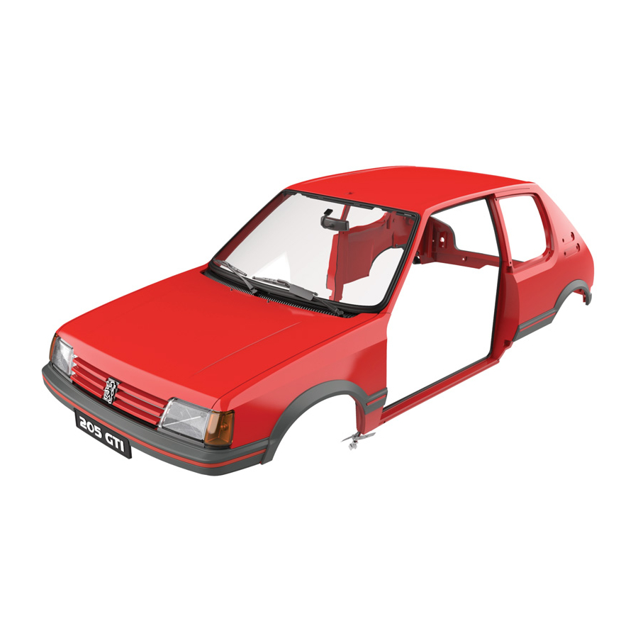
- Page 16 Saloon mounted on Chassis . Undo four screws to remove two spacer bars from 64A Body frame .
- Page 17 Final views .
- Page 18 Assembly drawings .
Need help?
Do you have a question about the 64A and is the answer not in the manual?
Questions and answers