Advertisement
Table of Contents
- 1 Table of Contents
- 2 Congratulations
- 3 Pbwt -On C I M Q
- 4 Amplifiers and 2 Ohm Operation
- 5 Electrical Wiring
- 6 Mounting the Amplifier
- 7 Remote Subwoofer Level Control
- 8 Tvo Channel Speaker Wiring
- 9 Bridged Speaker Wiring with Two Channel Amplifier
- 10 Tri-Mode Speaker Wiring with Two Channel Amplifier
- Download this manual
Advertisement
Table of Contents

Related Manuals for Boss Audio Systems Ripper RIP-496


Summary of Contents for Boss Audio Systems Ripper RIP-496
-
Page 2: Table Of Contents
A N U A L High Input Wiring Bridged Speaker Wiring With Two Channel Amplifier Tri-Mode Speaker Wiring With Two Channel Amplifier Bridged Speaker Wiring With Four Channel Amplifier Dual Tri-Mode Speaker Wiring With Four Channel Amplifier CONTENTS Congratulations! Specifications Features C i m q pbwt... -
Page 3: Congratulations
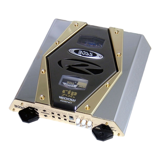
Congratulations on your purchase of a BOSS@ Audio Systems RIPPER car audio amplifier. RIPPER amplifiers are designed in the USA to the highest level of quality, and will afford you years of listening enjoyment. All RIPPER amplifiers utilize fully-regulated MOSFET power supplies, which assure that switching response is extremely fast and output power is clean. -
Page 4: Features
7buo Channel Amplifiers: RIP496, RIP596, RIP696 Heavy Duty Aluminum Alloy Heatsink Class A-B Operation Variable Low and High Pass Crossovers Variable Bass Boost Control (0 +18dB) Gold-Plated RCA Low Level and High Level Inputs Line Output Jacks Variable Phase Shift Control (0 - 180') Remote Turn On/Turn Off Circuit MOSFET Pulse Width Modulated (PWM) Power Supply 2 Ohm Stable Stereo Operation with Output Power Increase... -
Page 5: Protection Circuitry
Built in Crossover All RIPPER amplifiers feature built-in electronic crossovers. The 2 Channel (RlP496/596/696) amplifiers feature an adjustable low pass and high pass crossover and +18dB variable Bass Boost. The 4 Channel (RlP796/896) amplifiers feature a pair of individually adjustable low pass crossovers and high pass crossovers, as well as +18dB variable Bass Boost. -
Page 6: Electrical Wiring
Electrical Wiring All BOSS power amplifiers are equipped with "easy-access" screw terminals. These terminals are nickel- plated to ensure excellent electrical contact and resist corrosion. When making electrical connections t o the amplifier, please observe the following: Use at least 8 gauge or heavier wire for power and ground connections. Connect the amplifier directly to the car battery. -
Page 7: Remote Subwoofer Level Control
High Level Inputs If the HIGH LEVEL INPUTS are used, do not use the LOW LEVEL RCA INPUTS at the same time. The RIPPER 2-Channel amplifiers use ONE HIGH LEVEL INPUT for both channels and the RIPPER 4-Channel amplifiers use TWO of these connectors one for each pair of channels. LOW PASS MODE ONLY. - Page 8 Input /Line Out Level The RCA jacks marked "INPUTS" should be connected the low-level output of your source unit. jacks marked "LINE OUT" will pass the signal that is present on the amplifier inputs, facilitating the connection of additional amplifiers along. TWO Channel Amplifiers: RIP496, RIP596, RIP696...
-
Page 9: Two Channel Speaker Wiring
Two Channel Speaker Wiring Tbuo Channel Amplifiers: RIP496, RIP596, RIP696 " I GROUND to REMOTETurn-on from HEAD UNIT Bridged Speaker Wiring Tho Channel Amplifiers: RIP496, RIP596, RIP696 GROUND^ to REMOTE Turn-on from HEAD UNIT to BATTERY LEFT SPEAKER RIGHT SPEAKER Connect the NEGATIVE SPEAKER TERMINAL to thc RIGHT CHANNEL NEGATIVE AMPLIFIER TERMINAL Connect the POSITIVE SPEAKER TERMINAL to the... -
Page 10: Speaker Impedance
Four Channel Speaker Wiring Four RIP796 and RIP896 Bridged Speaker Wiring Four RIP796 and RIP896 to REMOTE Turn-on from HEAD UNIT Channel Amplifiers: Channel Amplifiers: SPEAKER IMPEDANCE OHMS1... -
Page 11: Tri-Mode Speaker Wiring With Two Channel Amplifier
Dual mi-Mode Speaker Wiring Four Channel Amplifiers: RIP796 and RIP896 Tri-Mode Operation is a unique feature which allows a subwoofer to be operated in MONO mode, while the main speakers are playing in STEREO simultaneously on one pair of amplifier output channels. - Page 12 Precautions Before you drill or cut any holes, investigate your car's layout very carefully. Take care when you work near the gas tank, fuel lines, hydraulic lines and electrical wiring. Do not operate the amplifier when securely within the automobile to prevent damage. Do not mount this amplifier so that the wire connections are unprotected or in a pinched condition, or likely to be damaged by nearby objects.
-
Page 13: Troubleshooting
Troubleshooting Before removing your amplifier, refer to the list below and follow the suggested procedures. Always test the speakers and their wires first. No Output Confirm that all terminal strip connections are secure and tight. Check both in-line and built-in fuses. Both the have +12v referenced to chassis ground.
Need help?
Do you have a question about the Ripper RIP-496 and is the answer not in the manual?
Questions and answers