
Related Manuals for LINDR SODA PYGMY GREEN LINE


Summary of Contents for LINDR SODA PYGMY GREEN LINE
- Page 1 INSTRUCTION MANUAL SODA WATER MAKERS LINDR ENGLISH Number 015-2020 REV00 Valid 2020-07-01...
- Page 2 Sadová 132 503 15 Nechanice, Czech Republic mob.: + 420 775 715 494 tel. : +420 495 447 239 e-mail: info@lindr.cz web: www.lindr.cz, www.lindr.eu SYMBOLS AND MARKINGS USED IN THE MANUAL: WARNING: NOTE: Not following instructions may cause injury or This symbol indicates information and re- damage the device.
-
Page 3: Table Of Contents
Obsah: Introduction ........Description of the device ........Machine plate .. -
Page 4: Introduction
1. INTRODUCTION: General safety principles. Observe the fo- Thank you for purchasing this LINDR product. llowing safety instructions. 2. DESCRIPTION OF THE DEVICE: The supplier is not liable for damage caused Soda Water Makers: by activities carried out on this device without... -
Page 5: Installation And Placement
WARNING: Never place tools or other ob- WARNING: After unpacking, place the coo- ject into the fan. ler so that heat created by the cooling unit can be vented sufficiently. WARNING: Never touch electrical compo- WARNING: Do not place objects that could nents with wet or damp hands. -
Page 6: Electrical Connection
9. CONNECTION AND PRESSURISATION: SODA PYGMY GREEN LINE 9.1 Connection and Pressurisation 1. Water inlet 3/8 6. Main water connection (drinking water) 2. Inlet of CO 7. - Page 7 SODA PYGMY 25 GREEN LINE 9.2 Connection and Pressurisation 1. Water inlet 7. Water hose 2. Inlet of CO 8. CO hose 3. Pressure reducer CO 9. Python 4. Water Filter 10. Speed fitting 9,5 x 8 mm 5. Main water connection (drinking water) 11.
- Page 8 SODA AS-45 GREEN LINE 9.4 Connection and Pressurisation 1. Beverage inlet for chilling 7. Main water connection (drinking water) 2. Water inlet for production of carbo- 8. Keg coupler (A-system, S-system, M-system) nated water 9. Beverage 3. Inlet of CO 10.
- Page 9 SODA AS-110 GREEN LINE 9.6 Connection and Pressurisation 1. Water inlet 10. Pressure reducer for water 2. Inlet of CO 11. Pressure reducer for 2 st. CO 3. Water inlet for chilling 12. Y 8 x 8 x 8 mm speed fitting 4.
-
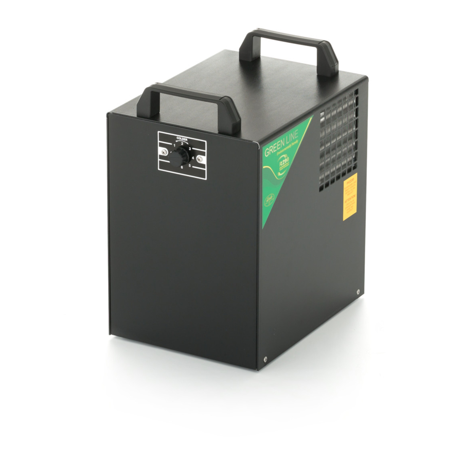
Page 10: Temperature And Adjustment
10. TEMPERATURE AND ADJUSTMENT : TThe temperature of the cooled beverage is controlled by a mechanical thermostat in temperature range of 2 °C to 8 °C. The thermostat has a numerical scale of 1-7. 10 A 10 B 10 C figure figure figure... -
Page 11: Water Pressure Reducer
12. WATER PRESSURE REDUCER: 11 A figure The MRA 1 / 4-8m regulator is recommended for the correct operation of the device. ( for SODA PYGMY 25 GREEN LINE it is part of the device ) 1. regulator 2. speed fitting JG M 1/4 x 9,5 mm 3. -
Page 12: Keg Tapping And Untapping
11.2 Outlet for Beverage : Screw an F 5/8“ x 3/8“ (9,5 mm) speed fitting onto the keg coupler. 5/8“-3/8“(9,5mm) 5/8“-5/16(8mm) 14. KEG TAPPING AND UNTAPPING: 14.1 Keg Tapping: WARNING: Make sure the Procedure for tapping a keg using an S-system keg coupler: adapter is clean before tapping the keg! S-system keg coupler... - Page 13 13 A 13 b figure figure 13 c 13 d figure figure 13 e figure 14.2 Keg Untapping: Procedure for untapping a keg using an S-system keg coupler: 13 f 13 g figure figure...
- Page 14 14 A figure 14.3 Keg Tapping: Procedure for tapping a keg using an A-system keg coupler: WARNING: Make sure the adapter is clean before A-system keg coupler tapping the keg! 14 c figure figure 14 d 14 e figure figure...
-
Page 15: Putting Into Operation
5. Connect the device to the power mains. 6. Switch on the device with the main switch (use thermostat for the SODA PYGMY GREEN LINE model). 7. You can use the tap to dispense a drink. -
Page 16: Table Of Malfunctions
17. TABLE OF MALFUNCTIONS: Malfunction Cause Removal The soda water does Pressure at the inlet has Reduce the pressure on the water not flow. exceeded 3.0 bar. valve min. to 2.5 Bar.-max 3.0 Bar. No water supply to the wa- Open the valve on the water tap. -
Page 17: Spare Parts
Do not forget to specify the following: • type of defect • product type • production year • product‘s serial number (found on the machine plate) Ordering Components: ALWAYS USE ORIGINAL COMPONENTS. The manufacturer or supplier bear no responsibility for non-original components or components not recommended by the manufacturer. 18. -
Page 18: Periodic Checks
21. PERIODIC CHECKS: 1x a month: check the cooling unit‘s con- 1x a week: check that the lead-in cable is denser and clean it regularly. undamaged and that the plug is firmly in the socket. 1x a year: have an engineering inspector 1x a week: check that the device is not check the electrical safety of the device.
Need help?
Do you have a question about the SODA PYGMY GREEN LINE and is the answer not in the manual?
Questions and answers