
Related Manuals for AP Diving RBV07 Series

Summary of Contents for AP Diving RBV07 Series
- Page 1 AP Diving Ltd. RBV07 Swivel Inflator Range Maintenance Manual RBV07 Swivel Inflator Range Maintenance Manual Version 0.95 April 2019 Written by Tino de Rijk Page 1 of 50...
-
Page 2: Table Of Contents
AP Diving Ltd. RBV07 Swivel Inflator Range Maintenance Manual Table of Contents 1. Introduction ................... 4 1.1 Functional description ..................4 1.2 Servicing ......................4 1.3 Warranty ......................4 1.4 Copyright and Applicable Law ................ 4 3. RBV07 Swivel Inflator Range Exploded Diagrams and Parts Lists ..5 3.1 RBV07(A) Single Swivel Inflator main assembly .......... - Page 3 AP Diving Ltd. RBV07 Swivel Inflator Range Maintenance Manual 7.2 Place a new O-ring into the inflator body............36 7.3 Screw the blue or green push button onto the inflator spindle ...... 37 7.4 Fit a new O-ring onto the inflator body and locking ring ....... 39 7.5 Connect the inflator body to the outlet body ..........
-
Page 4: Introduction
EN14143 is unaffected by the fitting of this RBV07 Swivel inflators. The RBV07 swivel inflators meet the requirements of the Personal Protective Equipment Directive 89/686/EEC – CE certification when fitted to an AP Diving rebreather. WARNING: When servicing the RBV07 swivel inflators it is VERY important that all parts that may suffer wear and tear get replaced. -
Page 5: Rbv07 Swivel Inflator Range Exploded Diagrams And Parts Lists
AP Diving Ltd. RBV07 Swivel Inflator Range Maintenance Manual 3. RBV07 Swivel Inflator Range Exploded Diagrams and Parts Lists 3.1 RBV07(A) Single Swivel Inflator main assembly NUMBER DESCRIPTION PART NUMBER QUANTITY Push Button (Green or Blue) AP_43 Spring AP_43_A Inflator Spindle... -
Page 6: Rbv07(A)/Dual Dual Swivel Inflator Main Assembly
AP Diving Ltd. RBV07 Swivel Inflator Range Maintenance Manual 3.2 RBV07(A)/DUAL Dual Swivel Inflator main assembly NUMBER DESCRIPTION PART NUMBER QUANTITY Push Button (Green or Blue) AP_43 Spring AP_43_A Inflator Spindle AP_52_C BS-006-N70 O-ring BS_006_N70 BS-010-N70 O-ring BS_010_N70 BS-111-N70 O-ring... -
Page 7: Rbv07(A)/So Single Swivel Inflator With Shutoff Valve Main Assembly
AP Diving Ltd. RBV07 Swivel Inflator Range Maintenance Manual 3.3 RBV07(A)/SO Single Swivel Inflator with Shutoff Valve main assembly NUMBER DESCRIPTION PART NUMBER QUANTITY Push Button (Green or Blue) AP_43 Spring AP_43_A BS-006-N70 O-ring BS_006_N70 BS-010-N70 O-ring BS_010_N70 BS-111-N70 O-ring... -
Page 8: Rbv07(A)/Dual/So Dual Swivel Inflator With Shutoff Valve Main Assembly
AP Diving Ltd. RBV07 Swivel Inflator Range Maintenance Manual 3.4 RBV07(A)/DUAL/SO Dual Swivel Inflator with Shutoff Valve main assembly NUMBER DESCRIPTION PART NUMBER QUANTITY Push Button (Green or Blue) AP_43 Spring AP_43_A Inflator Spindle AP_52_C BS-006-N70 O-ring BS_006_N70 BS-010-N70 O-ring... -
Page 9: General Information
AP Diving Ltd. RBV07 Swivel Inflator Range Maintenance Manual 3. General Information 3.1 Four versions There are four versions of the RBV07 Swivel inflator within the range. All four versions are available in both a Diluent as well as an Oxygen model, making a total of eight different models. -
Page 10: Dual Swivel Inflators - Rbv07/Dual & Rbv07A/Dual
AP Diving Ltd. RBV07 Swivel Inflator Range Maintenance Manual 3.4 Dual Swivel Inflators - RBV07/DUAL & RBV07A/DUAL The RBV07(A)/DUAL has two MP inlets and one MP outlet. Both inlets rotate to facilitate connection to wherever the gas sources are located. -
Page 11: Single Swivel Inflators With Flowstop Shutoff - Rbv07/So & Rbv07A/So
AP Diving Ltd. RBV07 Swivel Inflator Range Maintenance Manual 3.5 Single Swivel Inflators with Flowstop Shutoff - RBV07/SO & RBV07A/SO The RBV07(A)/SO has one MP inlet and two MP outlets. The central outlet is “straight-through”, which means the gas always flows from the inlet to this outlet regardless of the push button operation. -
Page 12: Dual Swivel Inflators With Shutoff - Rbv07/Dual/So & Rbv07A/Dual/So
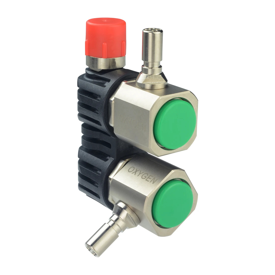
AP Diving Ltd. RBV07 Swivel Inflator Range Maintenance Manual 3.6 Dual Swivel Inflators with Shutoff - RBV07/DUAL/SO & RBV07A/DUAL/SO The RBV07(A)/DUAL/SO has two MP inlets and two MP outlets. The central outlet is “straight-through”, which means the gas always flows from the inlet to this outlet regardless of the push button operation. -
Page 13: Recommended Position Of The Collar Of The Gc3 Flowstop
AP Diving Ltd. RBV07 Swivel Inflator Range Maintenance Manual 3.7 Recommended Position of the Collar of the GC3 Flowstop The GC3 Flowstop gas isolator features a knurled slider which functions to open or close off the gas flow. The orientation of this slider determines which slider direction is open and which is closed. -
Page 14: Service Kit Contents And Tools
2) is ESSENTIAL for proper operation. If, against our recommendation, you choose to select your O-rings to come from another source than AP Diving Ltd., make sure you select the right type in size AND hardness AND material (composition). -
Page 15: Tools Needed
AP Diving Ltd. RBV07 Swivel Inflator Range Maintenance Manual 4.2 Tools Needed There are no special tools needed for servicing the RBV07 Swivel inflator. Normal tools needed are: A 5mm Allen key 8, 12,13, 14 and 24mm spanners A torque wrench for low torque settings (down to 4 Newton Meter) -
Page 16: Disassembly Instructions
AP Diving Ltd. RBV07 Swivel Inflator Range Maintenance Manual 5. Disassembly Instructions 5.1 General overview: main disassembly steps Despite the fact that all eight models of the RBV07 range of inflators have different layouts and functionality, the service procedures for these inflators have a lot in common. For that reason, the disassembly steps of the 8 different models are not described separately for each one, but are consolidated into steps that are common to all. -
Page 17: Unscrew The Gc3 Flowstop Isolator From The 5/16"-9/16" Adapter
Use a 14 mm spanner to unscrew the GC3 Flowstop from its adapter. NOTE: the service procedure for the GC3 Flowstop gas isolator is described in a separate AP maintenance manual, available on the AP Diving website. If the adapter becomes unscrewed from the inflator body in the process: don’t worry, as the adapter also needs to be unscrewed anyway. -
Page 18: Unscrew The 5/16"-9/16" Adapter(S) From The Outlet Body Or Inflator Body
AP Diving Ltd. RBV07 Swivel Inflator Range Maintenance Manual 5.4 Unscrew the 5/16”-9/16” adapter(s) from the outlet body or inflator body Use a 5 mm Allen key to unscrew the adapter from the single or dual outlet body or inflator body, counter-clockwise. -
Page 19: Remove The Inflator Body From The Outlet Body
AP Diving Ltd. RBV07 Swivel Inflator Range Maintenance Manual 5.5 Remove the inflator body from the outlet body Use a permanent marker to place a small mark on both the locking ring and the outlet body. This serves to later on, during assembly, act as an indicator as to how far to screw the locking nut back into the outlet body. - Page 20 AP Diving Ltd. RBV07 Swivel Inflator Range Maintenance Manual Avoid the use of an adjustable spanner, as it might damage the coating of the inflator body and locking ring. Remove the large O-ring from the stem of the inflator body, discard it and subsequently lift the locking nut from the inflator body.
-
Page 21: Unscrew The Blue Or Green Push Button From The Inflator Spindle
AP Diving Ltd. RBV07 Swivel Inflator Range Maintenance Manual 5.6 Unscrew the blue or green push button from the inflator spindle Use a non-slip surface that has sufficient gliding resistance, like a piece of rubber from a car or bike inner tube. - Page 22 AP Diving Ltd. RBV07 Swivel Inflator Range Maintenance Manual NOTE: there is a small number of early RBV07s in the field that have inflator spindles without a groove. These spindles can be removed by pushing on the push button, so that the inflator spindle sticks out.
-
Page 23: Remove The O-Ring From The Inflator Body
AP Diving Ltd. RBV07 Swivel Inflator Range Maintenance Manual Remove the O-ring from the inflator spindle and discard it. 5.7 Remove the O-ring from the inflator body Use a dental pick or similar device to remove the O-ring from the inflator body. - Page 24 AP Diving Ltd. RBV07 Swivel Inflator Range Maintenance Manual This completes the disassembly of the inflator assembly with its inlet and outlet adapters. Page 24 of 50...
- Page 25 AP Diving Ltd. RBV07 Swivel Inflator Range Maintenance Manual Page 25 of 50...
-
Page 26: Remove Low Profile Counterlung Inlet Elbow From Counterlung
AP Diving Ltd. RBV07 Swivel Inflator Range Maintenance Manual 5.8 Remove low profile counterlung inlet elbow from counterlung Unscrew (counter clockwise) the knurled locking ring that holds the low profile counterlung inlet elbow attached to the inlet base on the back-mounted counterlungs. -
Page 27: Remove O-Rings From Mp Counterlung Inflator Hose
AP Diving Ltd. RBV07 Swivel Inflator Range Maintenance Manual 5.9 Remove O-rings from MP counterlung inflator hose Unscrew (counter clockwise) the MP hose from the inlet elbow. Remove the O-rings from the MP hose. 5.10 When GC3 Flowstop is fitted: remove O-rings from both ends of MP... -
Page 28: Ap50 Medium Pressure (Mp) Hose Disassembly
AP Diving Ltd. RBV07 Swivel Inflator Range Maintenance Manual AP50 Medium Pressure (MP) hose disassembly 5.11 Remove circlip from snap connector body Use small pliers to remove the circlip from the snap connector body. Take care not to widen the circlip, as it will otherwise not be usable again during assembly. -
Page 29: Remove 4 Ball Bearings From Snap Connector Body
AP Diving Ltd. RBV07 Swivel Inflator Range Maintenance Manual 5.14 Remove 4 ball bearings from snap connector body Use a small tray to catch the 4 ball bearings to avoid losing them. 5.15 Unscrew Schraeder valve from snap connector body Use the AP50E tool or equivalent to unscrew the Schraeder valve from the body. -
Page 30: Remove O-Ring From Snap Connector Body
AP Diving Ltd. RBV07 Swivel Inflator Range Maintenance Manual 5.16 Remove O-ring from snap connector body Use a curved O-ring pick to remove this O-ring. This O-ring needs to be replaced during service. This completes the disassembly of the AP50 Medium Pressure hose. -
Page 31: Clean And Replace Service Parts
40% as the maximum percentage that is allowed for equipment that is not in oxygen service. AP Diving advises to err on the side of safety, and to use the value of 23.5% as the cutoff percentage beyond which the equipment must be in oxygen service. - Page 32 AP Diving Ltd. RBV07 Swivel Inflator Range Maintenance Manual Dual Diluent Swivel Inflator + outlet Hose + Counterlung RBV07/DUAL/KIT Inlet Service Kit [Note: Does not include any AP50 snap-connector Hose service parts – sold separately – see AP50KIT BS006N70 O Ring...
-
Page 33: Ultrasonically Clean Deposits From All Metal Parts
AP Diving Ltd. RBV07 Swivel Inflator Range Maintenance Manual Outlet Hose: BS903N70 O Ring BS010N70 O Ring Counterlung Inlet Base: BS222N50 O Ring for AP35E Din post base Dual Diluent Swivel Inflator (with Shutoff) + outlet Hose + RBV07/DUAL/SO/KIT Counterlung Inlet + Flowstop outlet-Hose Service Kit [Note: Does not include a GC3A Flowstop Service Kit or any AP50 Hose service parts –... -
Page 34: Replace All O-Rings With New Ones From The Service Kit
AP Diving Ltd. RBV07 Swivel Inflator Range Maintenance Manual 6.2 Replace all O-rings with new ones from the Service Kit WARNING: Replace all O-rings: do NOT re-use old ones. ONLY use original parts from APD, to make sure the O-rings:... - Page 35 AP Diving Ltd. RBV07 Swivel Inflator Range Maintenance Manual Drop them in the grease bag, and from the outside of the bag move them around with your fingers, making sure they get in full contact with the grease. Open the bag, and using a clean instrument like a dentist hook, take the now properly greased O-rings out.
-
Page 36: Assembly Instructions
AP Diving Ltd. RBV07 Swivel Inflator Range Maintenance Manual 7. Assembly Instructions WARNING: When assembling the RBV07 Swivel inflator, use rubber gloves to avoid contaminating it while assembling, rendering it not oxygen-clean anymore. This applies especially to the oxygen versions of the RBV07. -
Page 37: Screw The Blue Or Green Push Button Onto The Inflator Spindle
AP Diving Ltd. RBV07 Swivel Inflator Range Maintenance Manual 7.3 Screw the blue or green push button onto the inflator spindle Fit new O-rings onto the inflator spindle. Fit a new push button. ATTENTION: always use a new push button during service; NEVER reuse the old one. - Page 38 AP Diving Ltd. RBV07 Swivel Inflator Range Maintenance Manual Place the inflator body over the push button and its fitted spring, and push the assembly down onto the non-slip rubber surface. The aim of the rubber surface is to prevent rotation of the push button while screwing the inflator spindle back into the push button.
-
Page 39: Fit A New O-Ring Onto The Inflator Body And Locking Ring
AP Diving Ltd. RBV07 Swivel Inflator Range Maintenance Manual 7.4 Fit a new O-ring onto the inflator body and locking ring Push the locking nut over the stem of the inflator body, with the thread of the locking nut facing to the outside. -
Page 40: Connect The Inflator Body To The Outlet Body
AP Diving Ltd. RBV07 Swivel Inflator Range Maintenance Manual 7.5 Connect the inflator body to the outlet body Clamp the outlet body into a bench vice. ATTENTION: when using the vice, make sure to fit it with soft jaws (plastic or fibre). -
Page 41: Screw The 5/16"-9/16" Adapter(S) Back Into The Outlet Body Or Inflator Body
AP Diving Ltd. RBV07 Swivel Inflator Range Maintenance Manual 7.6 Screw the 5/16”-9/16” adapter(s) back into the outlet body or inflator body Fit new O-rings onto the base of the adapter(s). Use a 5 mm Allen key to screw the adapter back into the outlet body or inflator body. - Page 42 AP Diving Ltd. RBV07 Swivel Inflator Range Maintenance Manual Special care needs to be taken when refitting the 5/16”-9/16” adapter into the synthetic dual outlet body. Use a 5 mm torque wrench to nip up the 5/16”-9/16” adapter into the dual outlet body.
-
Page 43: Screw The Gc3 Flowstop Isolator Back Into The 5/16"-9/16" Adapter
AP Diving Ltd. RBV07 Swivel Inflator Range Maintenance Manual 7.7 Screw the GC3 Flowstop isolator back into the 5/16”-9/16” adapter ATTENTION: This step only applies to the RBV07(A)/SO and RBV07(A)/DUAL/SO versions of the inflator, which are fitted with a GC3 in-line gas isolator. -
Page 44: Fit New O-Rings To Mp Counterlung Inflator Hose
AP Diving Ltd. RBV07 Swivel Inflator Range Maintenance Manual This completes the assembly of the inflator assembly with its inlet and outlet adapters. 7.9 Fit new O-rings to MP counterlung inflator hose Fit new O-rings onto the MP hose. Screw (clockwise) the MP hose back into the inlet elbow. -
Page 45: Fit Low Profile Counterlung Inlet Elbow Back Onto Counterlung
AP Diving Ltd. RBV07 Swivel Inflator Range Maintenance Manual 7.10 Fit low profile counterlung inlet elbow back onto counterlung Place a new large sealing O-ring in the counterlung inlet base. Screw (clockwise) the knurled locking ring that holds the low profile counterlung inlet elbow back onto the inlet base of the back-mounted counterlungs. -
Page 46: When A Gc3 Flowstop Is Fitted: Fit New O-Rings To Both Ends Of Mp Hose
AP Diving Ltd. RBV07 Swivel Inflator Range Maintenance Manual 7.11 When a GC3 Flowstop is fitted: fit new O-rings to both ends of MP hose Fit new O-rings to both hose ends. ATTENTION: make sure to fit the hose the correct way around. Notice that the ends are different: o The end with the protruding connection goes onto the solenoid;... -
Page 47: Place The Yellow Locking Strap Back Onto The Gc3 Isolator
AP Diving Ltd. RBV07 Swivel Inflator Range Maintenance Manual 7.12 Place the yellow locking strap back onto the GC3 isolator. When fitting the locking strap to the Flowstop/hose assembly, it is important to fit the loop above the knurled area of the hose end. If it is fitted below the hose end, the strap can slide off easily and may impede the path of the black knurled slider, preventing its proper operation (see below right). -
Page 48: Screw New Schraeder Valve Into Snap Connector Body
AP Diving Ltd. RBV07 Swivel Inflator Range Maintenance Manual 7.14 Screw new Schraeder valve into snap connector body Use tool AP50E or equivalent to screw a new Schraeder valve into the snap connector body. Screw clockwise. Do not use force. -
Page 49: Push Sliding Collar Onto Snap Connector Body
AP Diving Ltd. RBV07 Swivel Inflator Range Maintenance Manual 7.17 Push sliding collar onto snap connector body The collar can only go on in one way. Push it on with the wider opening facing the hose and the smaller opening facing the circlip, to be fitted in the next step. -
Page 50: Testing Instructions
AP Diving Ltd. RBV07 Swivel Inflator Range Maintenance Manual 8. Testing Instructions 8.1 Test for leaks and proper operation Close the GC3 Flowstop slider (i.e. pull slider towards the "CLOSE" position), when fitted. Attach MP hoses to the inlet inflator stems and pressurise them.
Need help?
Do you have a question about the RBV07 Series and is the answer not in the manual?
Questions and answers