
Subscribe to Our Youtube Channel
Related Manuals for PTZ Optics PT-JOY-G4

Summary of Contents for PTZ Optics PT-JOY-G4
- Page 1 A 4th-Generation Network or Serial Camera Controller PT-JOY-G4 User Guide V1.0 Please check ptzoptics.com for the most up to date version of this document...
- Page 2 Thank You! Thank you for selecting our joystick camera controller built to support either IP or serial communication. As you read through this manual it will help identify the options you have for setting up the device, connecting equipment as well as recommended configurations; as a result we recommend reading over this guide prior to beginning any setup to have the best possible experience.
-
Page 3: What's In The Box
Introducing the PT-JOY-G4 The PT-JOY-G4 is designed to provide in depth control of the PTZOptics and HuddleCamHD line of cameras for use in production environments and more. With the ability to support either IP or Serial control from a single controller, the PT-JOY-G4 presents itself as a flexible control solution. -
Page 4: Table Of Contents
Table of Contents Preface Copyright Notice What’s in the Box Introducing the PT-JOY-G4 How to care for your PT-JOY-G4 Table of Contents PT-JOY-G4 Overview Top Down View & Layout Button & Dial Descriptions Rear Panel View & Layout Technical Specifications... -
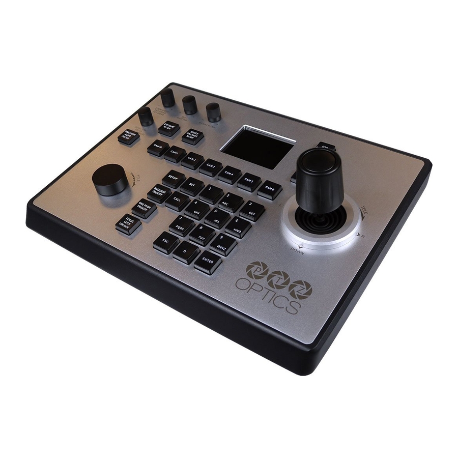
Page 5: Pt-Joy-G4 Overview
PT-JOY-G4 Overview Top Down View & Layout 1. Speed Control 7. Zoom Control 2. Exposure Control 8. Controller OSD Setup button 3. White Balance Control 9. Fine Tune Video Control 4. Camera OSD Control 10. Preset Control Buttons 5. Focus Control 11. -
Page 6: Button & Dial Descriptions
Button & Dial Descriptions The below descriptions will describe the buttons and dials available on the controller. 1. Speed Control The Speed Control section allows you to adjust the speed at which you pan, tilt, and zoom the camera. a. [SPEED] Knob Twist the Speed Control knob to increase or decrease the set control speed. - Page 7 a. [CAM ID] Button The [CAM ID] button allows you to select any camera on the controller using the alpha-numeric keypad. b. [CAM #] Button The [CAM #] button allows you to quickly select a camera to control. Options include: 1 - 6 7.
-
Page 8: Rear Panel View & Layout
Rear Panel View & Layout 1. RS-232 Control Connection 2. RS-422 / RS-485 Control Connection Refer to the Physically Connecting a Camera to the Controller section of this guide for more information. 3. Ethernet / RJ-45 (PoE) Network Connection Supports 802.3af PoE power 4. -
Page 9: Technical Specifications
Technical Specifications Network: NIC (TCP and UDP) Control Interfaces Serial: RS-232 Full Duplex, RS-485 Semi Duplex, RS-422 Full Duplex PTZOptics VISCA and VISCA over IP Protocols PELCO-D and PELCO-P via Serial Ports Limited Sony VISCA and VISCA over IP support Variable Baud Rate 1200 to 19200 bps Ethernet: 328 feet | 100 Meters... -
Page 10: Preparing To Use The Joystick
Preparing to use the Joystick Installation & Setup Power You can power your joystick using the included power supply or Power over Ethernet (802.3af). After applying power make sure that the I/O switch is flipped to “I” for “On”. Do not power the joystick controller using PoE and the power supply at the same time. Physically Connecting a Camera to the Controller To connect to a camera, you first need to decide which supported control method you need Network Control: To control your camera(s) over a network, connect an ethernet cable from your Local Area... -
Page 11: Network Setup
Network Setup The PT-JOY-G4 will dynamically obtain an IP address upon connection to your LAN. If your network is not able to supply DHCP addresses you must assign a static IP address to the controller. To set a static IP address, follow the steps below. - Page 12 RS-232 Daisy-Chain connection RS-485 Daisy-Chain connection Home-Run To utilize a Home-Run setup, you will need to connect all the cameras to the controllers’ 5 port phoenix connector. Home-Run setups can be used with both RS-485 & RS-422. Please use the figures below for reference.
-
Page 13: Adding A Camera
RS-485 Home-Run connection When you first boot up the joystick it will be in the IP mode. To toggle between IP and Serial control, press and hold the joystick button for 3+ seconds. Adding a Camera From the Joystick To add a camera to the joystick from the OSD setup menu, follow the steps below. 1. -
Page 14: From The Web Interface
From the Web Interface To add a camera to the controller from the web interface, follow the steps below. 1. Type the IP address displayed on the controllers OSD into a web browser to access the web interface. 2. Type in the login credentials to access the joysticks WebUI configuration page. a. -
Page 15: Joystick Osd Menu Control
Joystick OSD Menu Control 1. Add Network Device Refer to the Adding a Camera section of this guide for more information. 2. Add Serial Device Refer to the Adding a Camera section of this guide for more information. 3. Device List ○... -
Page 16: Operating The Camera
Operating the Camera To begin remotely operating a camera, you will first need to use the Camera Select buttons to begin using the controller. Once selected, you will have full remote operation of the selected camera from the controller. Pan, Tilt, and Zoom Operation The controller supports variable speed pan / tilt / zoom control, which allows you to set the control speeds prior to use. -
Page 17: Adjusting The Camera's Image
Adjusting the Camera’s Image There are many options for adjusting the camera’s image which we will detail below You can adjust Exposure & White Balance settings, Iris, Shutter, Red & Blue Gain, Focus, & Backlight Compensation to achieve the desired image style and quality. ●... -
Page 18: Camera Osd Menu Control
3. Press 7 - 9 on the alpha-numeric keypad to call camera 3 presets 1 - 3 respectively. Basic Mode Basic Mode allows you to disable most of the capabilities of the PT-JOY-G4 and limit the control to the joystick and/or calling presets. -
Page 19: Joystick Web Interface
Joystick Web Interface Device Management The Device Management page, available from the controllers web interface, allows you to define new cameras and adjust already configured cameras. Camera: Joystick control address. Base options include: 1 - 7 (IP & Serial) Expanded options include 1 - 255 (IP only) IP: The IP address of the saved network camera. -
Page 20: Settings
Settings The Settings interface allows you to adjust the configuration of the joystick. Upgrade: Browse your PC and upgrade the joystick’s firmware to the latest version. Factory Restore: Restores the joystick to factory default settings. Restart: Restart the joystick. Import: Browse your PC and import joystick settings. Export: Export joystick settings to PC. -
Page 21: Troubleshooting And Extras
Troubleshooting and Additional Information Troubleshooting LCD Display shows “Control Failure” This can occur when the controller doesn’t receive a response from the camera. 1. Please check that the network jacks you are using are active. 2. Please check that the network cable you are using is not failing. 3. -
Page 22: Additional Information
Additional Information Warranty The PT-JOY-G4 includes a 2 Year Limited Warranty. This warranty covers all manufacturers defects, and any damage that is done to the joystick during shipping. This warranty does not cover physical damage to the joystick that is due to lack of proper care. If you have trouble with your joystick and wish to see if it is covered under the manufacturer's warranty, please contact our support team by submitting a ticket at http://help.ptzoptics.com.
Need help?
Do you have a question about the PT-JOY-G4 and is the answer not in the manual?
Questions and answers