
Subscribe to Our Youtube Channel
Related Manuals for Torklift A9003

Summary of Contents for Torklift A9003
- Page 1 IMPORTANT OWNER-OPERATOR INSTALLATION INSTRUCTIONS A9003, A9004, A9005, A9103, A9104, A9105 Version Number: 4, Date: 9/11/2019 By: CW TECH SUPPORT (800) 246-8132...
- Page 2 Suspension To significantly reduce body roll, sag and sway Torklift strongly recommends the StableLoad. Torklift International StableLoads improve safety, handling, and to help level your truck. More information can be found at (www.Torklift.com/stableload). If your truck is additionally equipped with suspension air bags Torklift cautions against over pressurization as this may lead to unsafe vehicle handling characteristics.
-
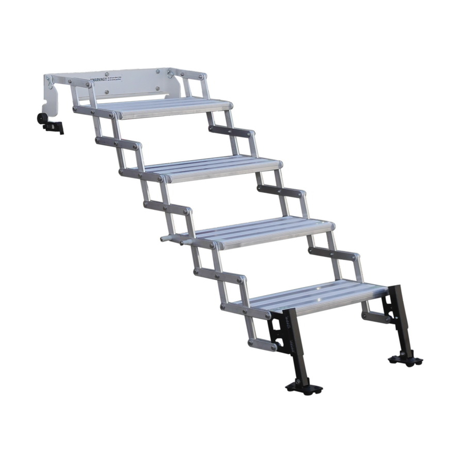
Page 3: Parts Inventory
Parts Inventory Item Image Item Description Item # A9003, A9004, A9005, Step Assembly A9103, A9104, A9105 A9003- Left Mounting Bracket P2-L A9003- Right Mounting Bracket P2-R 3/8” SS Flat Washer - 8949 3/8” Nylon Flat Washer 11748 3/8”-16 x 1-1/4” SS... -
Page 4: Installation
Installation Step 1 • Open the RV door as wide as possible. The door will need to open well passed 90 degrees to be able to install, store, and deploy the step system. • If the door is equipped with a gas strut limiting its travel, read the fire danger warning at the beginning of this manual. - Page 5 Step 2 • Remove the GlowStep Revolution Uprising (GSRU) from the packaging. • Extend the steps to their fully open position. Move the lower step latch lever to the right to unlock the lower step. (See figure 2.1) Main Bracket Expand Steps Move lever...
- Page 6 3/8”-16 Stainless 3/8” Stainless Steel Steel Nylock Nut SAE Flat Washer 3/8” Nylon Flat Washer Nylon Spacer 3/8” Nylon Flat Washer 3/8” Stainless Steel SAE Flat Washer 3/8”-16 x 1-1/4” Stainless Steel Button Head Bolt Figure 3.1 • Repeat the process for the left-hand side mounting bracket. Step 4 •...
- Page 7 Drill 3x 7/32” Holes Figure 4.1 Step 5 • Secure both left and right mounting brackets to the door frame flange using the hardware shown in Figure 5.1. #12-24 x 3/4” 3X #12 Stainless Steel Stainless Button Head Steel Nylock Screws Nuts 3X #12...
- Page 8 1/4” x 1” Stainless Steel Lag Screws Figure 5.2 Step 6 • Slide the GSRU main bracket in the mounting plate slots towards the inside of the door until the vertical portion of the main bracket contacts the threshold molding. (See figure 6.1) Tighten Hardware Push...
- Page 9 Operating the Steps Storing the GlowStep Revolution Uprising: Collapse the steps • Open the door as far as possible, it will need to be opened well passed 90 degrees. • Lift up on the bottom step until the Main Bracket begins to rotate up.
- Page 10 Store the steps • Rotate the collapsed steps up and into the RV. • Slide the safety latch to the right. The safety latch will keep the steps from rotating back out. (See Figure A.2) • Close the door. • NOTE: Screen door to door frame flange clearances do vary. In some instances, it may be necessary to modify the screen door frame to allow it to fully close.
- Page 11 Deploying the GlowStep Revolution Uprising • Open the door as far as possible, it will need to be opened well passed 90 degrees. • Slide the safety latch to the left to unlock the steps. • Rotate the collapsed steps outward. Do not allow the steps to fall freely.
- Page 12 Depress Depress Slide Slide Figure B.1 Deploying the Bottom Step • With the steps extended, move the lower lever to the right (See • Pull the bottom step down and away from the main step assembly (See Figure B.2) • Release the lever and expand the bottom step as far as possible. •...
- Page 13 Move Pull Figure B.2 Check for Pin Engagement (both sides) Move Figure B.3 Storing the Bottom Step. • Move the lower lever to the right • Push the bottom step in and upwards towards the RV • Release the lever and continue pushing the step upwards until the spring loaded pins lock the step in the stored position.
- Page 14 Setting the Hinge Tension The GSRU hinge tension was preset at the factory, however the tension may loosen with use over time. The hinge tension should be set so the steps operate smoothly, but will not expand on their own. •...
- Page 15 Screen Door Modification Screen door to door frame flange clearance does vary between trailers. In some instances, it will be necessary to clearance the screen door frame in order for it to fully close. • To clearance the screen door frame, start by storing the steps as described on page 9 and 10.
- Page 16 • Extend the marked lines around the corners of the frame 3/16”, then Connect the lines. See Figure D.2. Marked area for removal Figure D.2 • Using a Dremel or similar rotary tool, cut along the marked lines using a cutoff wheel.
- Page 17 Some states do not allow the exclusion or limitation of incidental or consequential damages, so the above limitation or exclusion may not apply to you. Any damage to Torklift products as a result of misuse, abuse, neglect, accident, improper installation or any use violation of instructions furnished by Torklift or WHEN USED IN ANY COMMERCIAL APPLICATION WILL VOID THE WARRANTY.
- Page 18 International gift. To Fax: Send copies of the questionnaire, warranty card and receipt to 253-854-8003 To E-mail: Send copies of the questionnaire, warranty card and receipt to warranty@torklift.com To Mail: Send to Torklift International 322 Railroad Ave North, Kent, WA 98032...
- Page 19 OFFICIAL WARRANTY REGISTATION CARD 322 Railroad Ave North, Kent, Wa 98032 Please fill out this form completely and return to Torklift within 30 days of purchase accompanied by a copy of your original receipt...
Need help?
Do you have a question about the A9003 and is the answer not in the manual?
Questions and answers