Table of Contents

Subscribe to Our Youtube Channel
Related Manuals for ABLE Ap1400-V


Summary of Contents for ABLE Ap1400-V
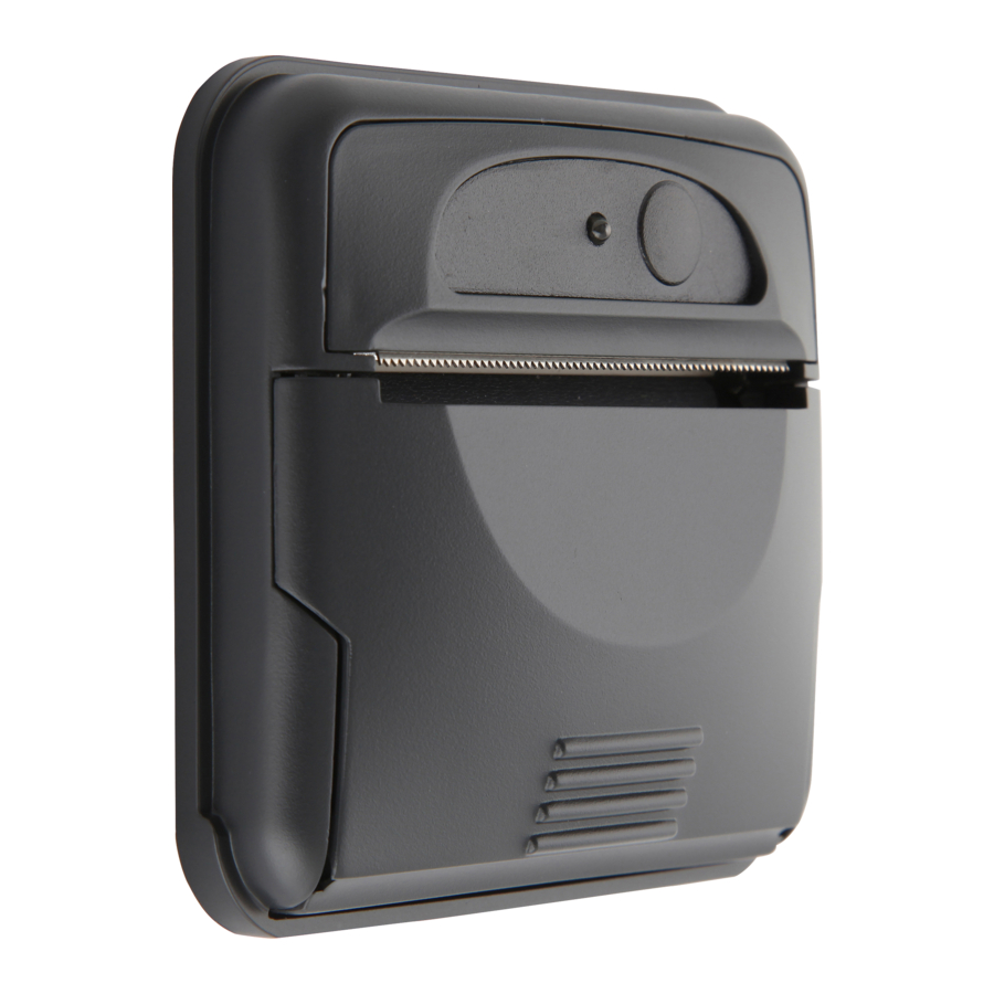
- Page 1 Experts in Small Printer Solutions Ap1400-V Thermal Printer Installer Guide Able Systems Limited Denton Drive, Northwich, Cheshire CW9 7TU England Tel: +44 (0) 1606 48621 Fax: +44 (0) 1606 44903 Web: www.able-systems.com...
-
Page 2: Table Of Contents
TABLE OF CONTENTS TABLE OF CONTENTS ..........................2 REVISION HISTORY ........................... 3 INTRODUCTION ............................3 ) ................3 OTES ON RINTER IRMWARE EVISIONS NCLUDING LASH ......................3 OPYRIGHT OTICE ISCLAIMER ..........................3 MPORTANT NFORMATION EMC STATEMENT AND CAUTION ......................4 ORDERING PART CODES, OPTIONS AND ACCESSORIES ................ -
Page 3: Revision History
3.1 NOTES ON PRINTER FIRMWARE REVISIONS (INCLUDING FLASH) Able Systems reserves the right to modify and improve the firmware in its printer products at any time. Whilst every effort is made to ensure backward compatibility, no guarantee in this respect is given or implied. -
Page 4: Emc Statement And Caution
3m long. ORDERING PART CODES, OPTIONS AND ACCESSORIES The following table details full Able Systems part codes for products related to the Ap1400 printer: DATA CABLES Ap1400SC... -
Page 5: Interface Details
In addition, the full printer command set is available to the programmer allowing much tighter tailoring of the printed output to suit this form of printer & application combination. Please contact Able Systems if you require the USB drivers or API interface. Ap1400V Installers’ Guide Page 5 of 15... -
Page 6: Power Supply Details
N.B. The average and peak current requirements can be adjusted by firmware control codes. See the Programmer Guide or contact Able Systems for details. The recommended power supply input is either a 12V or 24V vehicle battery, this allows the printer to perform at its best. -
Page 7: Connection Guide
6 and 8 TX data A moulded RS232 D9 lead for direct connection to a PC RS232 port can be obtained from Able by ordering part number: Ap1400D9. An unterminated RS232 lead can be obtained from Able by ordering part number: Ap1400SC. -
Page 8: J3 - Power
8.3 J3 – POWER J3 Mating Connector: Manufacturer: Molex Part Number: 51065-0600 Crimp Part Number: 0502128000 (24-30 AWG) Signal Description Positive 9-36V with overvoltage and reverse protection. (5A fuse required) (Connect to both V+ pins to avoid overloading the connector) 0V Common (RS-232 signal return and power supply common) (Connect to both GND pins to avoid overloading the connector) Shutdown input (Active Low - see section 8.5 for further details) -
Page 9: Shutdown Input
8.5 SHUTDOWN INPUT The shutdown input (J3, pin 5) is designed to be used with an Active Low input such as the ignition connection in a vehicle. The user shutdown function is disabled as standard, the printer defaults to awake at power on. To allow the user shutdown feature, the position of the jumper at site JP4 must first be altered, following this applying a voltage of +2V to +36V on the shutdown pin will keep the printer awake otherwise the printer will enter the sleep state. -
Page 10: Unit Dimensions
UNIT DIMENSIONS (All dimensions in mm) 10 MECHANICAL FIXINGS The Ap1400V has several fixing options to suit a variety of installations; 10.1 MOUNTING BRACKET 1) Fit the printer into the panel and apply the mounting bracket as shown below. 2) Secure with two M3 machine screws or two cable ties, one at either side of the bracket. (all included in Ap1400VKIT). -
Page 11: Front Fixing
10.2 FRONT FIXING 1) Open the lid of the printer and remove the two knock-outs using a small flat-headed screwdriver. 2) Prepare the panel aperture as described below. 3) Fit the printer to the panel and fix in place using two self-tapping screws as shown above (Ø 3mm max, included in Ap1400VKIT). -
Page 12: Fixing Orientations
The printer can therefore be mounted horizontally or angled to the limits shown below. Should you wish to use the Ap1400V in orientations that exceed these limits please contact Able Systems for advice. -
Page 13: Modes Of Operation
11 MODES OF OPERATION The Ap1400V has two operating modes, when not actually printing: "Idle Mode": ready to accept data, but no data in the buffer awaiting printing, and the printer motor is not running; "Spool Mode": active, but storing data for later printing. Modes are indicated by different colour combinations on the front-panel LED (see section 8). -
Page 14: Loading Paper
13.1 LOADING PAPER The procedure for loading paper is as follows: Press the lid in towards the panel. Unwind a small amount of paper from the roll and Insert the Paper Roll into the Printer. Close the Lid, and the paper is loaded. After loading, check that the paper is straight and advances properly, and tear off any excess by pulling the paper sharply towards you across the serrated tear bar. -
Page 15: Printer Operation And Programming
Various combinations of single or double width, single or double height, inverted, underlined, and other attributes may be mixed within a line. Customised fonts may be created using the Able Systems Font Editor Utility, and downloaded to the Ap1400V. Please contact the factory for more information.
Need help?
Do you have a question about the Ap1400-V and is the answer not in the manual?
Questions and answers