
Related Manuals for Aalborg DPC

Summary of Contents for Aalborg DPC
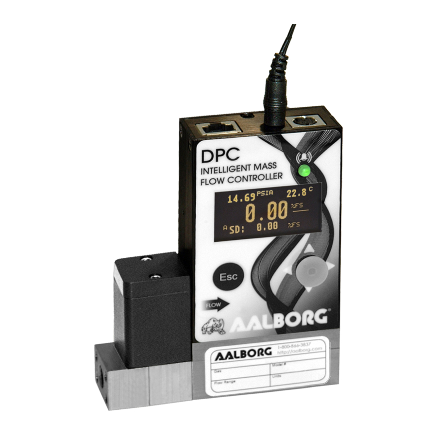
- Page 1 Technical Data Sheet No. TD-DPC-0F Date of Issue: October 2020 OPERATING MANUAL ® Aalborg Digital Mass Flow Controllers...
- Page 2 Aalborg® is a registered trademark of Aalborg® Instruments & Controls. NOTE: Aalborg® reserves the right to change designs and dimensions at its sole Discretion at any time without notice. For certifi ed dimensions please contact Aalborg®.
-
Page 3: Table Of Contents
TABLE OF CONTENTS 1. Unpacking the DPC Mass Flow Controller........1.1 Inspect Package for External Damage............ 1.2 Unpack the Mass Flow Controller............1.3 Returning Merchandise for Repair............2. INSTALLATION................ 2.1 Safety Instructions................. 2.2 Primary Gas Connections................2.3 Pressure Requirements................. 2.3.1 DPC 07/17/37/47/57/67/77 Pressure Requirements....... - Page 4 6.4.14 Submenu “Pulse Output”............. 6.4.15 General Settings................6.4.15.1 Valve Parameters..............6.4.15.2 STP/NTP Conditions..............6.4.15.3 Display and Process Information (PI) Screens......6.4.15.4 Submenu “Communication Port Settings”........ 6.4.15.5 Submenu “Modbus Interface” (optional)....... 6.4.15.6 Relay Assignment..............6.4.15.7 Analog Output Confi guration..........6.4.15.8 Analog Input Confi guration............ 6.4.15.9 Status LED Settings..............
-
Page 5: Unpacking The Dpc Mass Flow Controller
UNPACKING THE DPC MASS FLOW METER Inspect Package for External Damage Your DPC Mass Flow Controller was carefully packed in a sturdy cardboard carton, with anti-static cushioning materials to withstand shipping shock. Upon receipt, inspect the package for possible external damage. If the unopened package is damaged, contact the shipping company immediately to make a report. -
Page 7: Primary Gas Connections
CAUTION Some of the IC devices used in the DPC are static-sensitive and may be damaged by improper handling. When adjusting or servicing the device, use of a grounded wrist strap is recommended to prevent inadvertent damage to the integral solid-state circuitry. -
Page 8: Dpc04/14 "Breeze" Low Differential Pressure Models
9.75 PSID. The user shall install the instrument only in process lines that meet the DPC controller’s pressure and temperature ratings. A margin of safety should be provided if spikes and surges exist in the process. Proper pressure relief... -
Page 9: Mounting
fl at panels. See APPENDIX II for exact dimensions. The DPC Mass Flow Controller can be mounted in any position. It is not required to maintain straight runs of pipe upstream or downstream of the instrument. It is preferable to install the controller in a stable environment, free of frequent and sudden temperature changes, high moisture, and drafts. -
Page 10: Power Supply Connections
24 to 26 Vdc, with maximum load current at least 650 mA (unipolar power supply), and maximum ripple below 150 mV P-P. Power can be applied to the DPC controller either through the power jack or the 8-pin Mini- DIN connector (see Figure 1). -
Page 11: Analog Set Point Input Signals Connections
ON. Wiring error may cause damage or faulty operation. DPC series Mass Flow Controllers are equipped with calibrated 0-5Vdc, 0-10Vdc or 4-20 mA set point input signals. These linear input signals represents 0-100% of the fl ow con- troller’s full scale range. -
Page 12: Analog Output Signals Connections
ON. Wiring error may cause damage or faulty operation. DPC series Mass Flow Controllers are equipped with calibrated 0-5Vdc, 0-10Vdc or 4-20 mA output signals. This linear output signal represents 0-100% of the fl ow controller’s full scale range. - Page 13 (pin 5 on the host PC DB9 connector) ------ pin 1 (Sleeve) of the 3-pin stereo jack connector Each DPC ordered with RS-232 interface option is supplied with default crossover 1.5- foot long communication cable (AALBORG P/N: CBL-A232) DB9 female to stereo 3.5 mm Plug.
- Page 14 ------ pin 1 on 3-pin Audio-connector, the sleeve” section DPC (GND), (Shield wire) Each DPC ordered with RS-485 interface option is supplied with a default 3-foot length of communication cable (AALBORG P/N: CBL- A485DP) Stereo 3.5 mm plug to stripped wires.
-
Page 15: Principle Of Operation
FIGURE 5: DPC Mass Flow Controllers RS-485 Communication Interface Connections When the DPC device is set as the last device on the long RS-485 bus segment, the 120 bus termination resistor must be connected between the RS-485 (+) and (-) terminals close (<... -
Page 16: Specifications
OLED/Joystick interface, Digital Communication Interface (RS-232/RS-485, or optional Modbus), Programmable Table. The DPC fl ow controller can display fl ow rate in 43 different mass fl ow or 15 different volu- metric fl ow engineering units. Instrument parameters and functions can be programmed locally via optional OLED/Joystick interface or remotely via the RS-232/RS-485 interface or optional Modbus RTU interface. - Page 17 MASS REFERENCE CONDITIONS (STP): 70 °F & 14.696 PSIA (other references available on request). MAXIMUM INTERNAL GAS PRESSURE (STATIC): DPC07/17/37/47/57/67/77: 120 PSIG. DPC04/14: 50 PSIG. MAXIMUM INSTANTANEOUS DIFFERENTIAL PRESSURE ACROSS DIFFERENTIAL PRESSURE SENSOR: DPC07/17/37/47/57/67/77: 12 PSID. DPC04/14: 9.75 PSID PROOF PRESSURE: DPC07/17/37/47/57/67/77: 145 PSIG.
-
Page 18: Ce Compliance
Mass Flow, Totalizer Volume, Pressure and Temperature or Mass Flow, Volumetric Flow, Pressure and Temperature (user-selectable screens). For DPC with full scale 20 sml/min and lower or above 100 sl/min the response time may be slightly longer. CE Compliance EMC Compliance with 2004/108/EC as amended. CISPR11... -
Page 19: Dpc Accessories
TABLE II: DPC FLOW RANGES PRESSURE DROP MODEL FULL SCALE PROCESS AT FULL SCALE MASS FLOW RATE CONNECTION FLOW (PSID) DPC07 0.5 to 50 sml/min 1.25 10-32 female thread DPC17 51 sml/min to 20 sl/min 25.0 1/8" NPT female DPC37 21 sl/min to 50 sl/min 1/8"... - Page 20 Power Supply, 220 V / 24Vdc /Europe PS-GFM-240UK-2 Power Supply 240 V / 12 Vdc /United Kingdom CABLES Communication Cable for DPC with RS-232 Interface 1.5 FT CBL-A232 3.5mm stereo audio connector with 3-wire to 9-pin female D-connector (included with each DPC ordered with RS-232).
- Page 21 100.0 10546 15.0 103.421 DPC57 1758 17.237 DPC67 4851 47.57 DPC77 1000 10546 15.0 103.4 DPC (BREEZE) LOW PRESSURE DROP [AIR] DPC04 0.02 56.2 0.08 0.55 DPC14 133.6 0.19 1.31 TABLE V: APPROXIMATE WEIGHTS MODEL WEIGHT SHIPPING WEIGHT DPC04/07/14/17 1.40 lbs. (0.635 kg) 3.31 lbs.
-
Page 22: Operating Instructions
Figure 6: DPC fi rst Banner Screen Fw: A001 Tbl: A001 COM:RS232 Add: 11 Baud Rate: 9600 ModBus: Y Add: Figure 7: DPC Firmware and Communication Interface Informain Screen Absolute Pressing Absolute Pressure Units of Measure Reading Temperature Reading PSIA 14.67 14.67 27.7... -
Page 23: Swamping Condition
Temperature, Mass Flow reading, Set Point Value, Set Point Source and Valve Mode. NOTE: 5 seconds after the initial powering of the DPC controller, the status LED will emit a constant GREEN light (normal operation, ready to control). By default, unless “Local Set Point Auto Start" parameter is enabled (see Section 6.4.3), after power is applied to the instrument the controller’s Valve Mode set to “Closed”. - Page 24 sequencing with user-adjusted screen Cycle Time (see Section 6.4.15.3 “Display and Pro- cess Information (PI) Screens”). When the last PI screen is reached, the fi rmware “wraps around” and scrolls to the initial PI screen once again. In the Static Mode, moving the joystick Up pages through the PI screens in the forward di- rection, while moving the joystick DN pages through the PI screens in the reverse direction.
- Page 25 AP Sensor Temperature Raw Counts DP Sensor reading mBar DP: 0.005 DP: 0.005 0.0001 0.0001 DP sensor reading in PSID T: 26835 T: 26835 24.83C 24.83C Temperature Sensor Reading (deg. C) Temperature Sensor Raw Counts FIGURE 10: DPC PROCESS INFORMATION SCREENS...
-
Page 26: Local User Interface Menu Structure
Local User Interface Menu Structure The diagram in Figure 19 gives a general overview of the standard top- level display menu structure (when running fi rmware version A001). The Esc push-button is used to toggle be- tween the Process Mode (PI screens) and the Setup menus, and to return to upper menu level. In order to move through the menu items, the user must move the joystick UP and DN. -
Page 27: Parameter Entry
Once the correct password is entered, the Program Protection is turned off until the unit is powered up again. 6.4.1 Parameter Entry Direct numerical entry. There are two methods of data entry: Tabular Input from a menu. If the menu with direct numerical entry is selected, move the joystick UP or DN to increase or decrease digit value between 0-9. -
Page 28: Instrument Set Point And Valve Control
New PP Password has been saved PP Password is Changed Figure 14: PP Password Change Confi rmation Screen 6.4.3 Instrument Set Point and Valve Control In order to be able to change the Set Point value via Local OLED/Joystick interface the “Set Point Source”... - Page 29 fl ow rate and valve may reach very high temperature! DPC controller Valve Mode can be set in the one of the 3 following modes: Closed, Auto, Opened. The normal operating mode is “Auto”. While controller's Valve Mode set in “Auto”...
-
Page 30: Submenu "Control Pid Parameters
DPC instruments support 3 different implementations of the PID control loop algorithm: PD, PID and PIDD. The PD algorithm is the default algorithm used on most DPC controllers and usually works fi ne for most generic applications with wide range of the differential pressure across the valve. -
Page 31: Submenu "Device Information
Before starting “PID Auto Tune” procedure user should apply desired inlet pressure to the inlet of the DPC instrument and enter desired target “Set Point” value in %FS units. For most applications recommended set point values are between 50.0 and 90.0 %FS. -
Page 32: Submenu "Units Of Measure
6.4.6 Submenu “Units of Measure” Use the “Units of Measure" Menu to navigate to Measuring Units settings for Mass Flow, Volumetric Flow, Pressure, and Temperature readings. This option allows confi guration of the fl ow controller with the desired units of measurement. These are global settings and determine what appears on all Process Information screens and in all data log records. - Page 33 TABLE VI (CONTINUED): LIST OF SUPPORTED MASS FLOW UNITS OF MEASURE Mass Flow Rate Totalizer Volume Number Description Units Units TRUE MASS lb/min Pounds per minute lb/hr Pounds per hour lb/day Pounds per day oz/sec Ounce per second oz/min Ounce per minute NORMAL NuL/min Microliters per minute...
- Page 34 TABLE VII: LIST OF SUPPORTED VOLUMETRIC FLOW UNITS OF MEASURE Description Totalizer Volume Units Number Flow Rate Units Percent of Full Scale uL/min Microliters per minute mL/sec Milliliter per second mL/min Milliliters per minute mL/hr Milliliter per hour L/sec Liter per second L/min Liter per minute L/hr...
-
Page 35: Submenu User-Defi Ned Units
TABLE IX: LIST OF SUPPORTED TEMPERATURE UNITS OF MEASURE Number Temperature Units Label Description ˚F degree Fahrenheit ˚C degree Celsius Kelvin ˚R degree Rankine NOTE: Program the Measuring Units fi rst because subsequent menus may be based on the units selected. Once Flow Unit of Measure is changed, the Totalizer’s Unit of Measure will be automatically updated. - Page 36 Figure 19: DPC Upper Levels Menu Structure...
-
Page 37: Submenu "Select Gas
6.4.8 Submenu "Select Gas" The currently active gas can be selected by the user via OLED/joystick or digital communication interface. The gas data are allocated in different gas groups (see Figure 20 below). The “Recent Gases” group keeps up to 16 recently selected gases. The detailed list of the gases for each group is provided in Tables X through XVIII, beginning on the following page. - Page 38 TABLE X: Standard Pure Non-Corrosive Gases All Data for Standard Conditions (70 °F and 14.696 PSIA) Absolute Short Long Name Viscosity (µPa-s) Density g/l Compressibility Number Name 18.259686 1.2000185 0.99963453 Argon 22.377244 1.6555318 0.99932392 Carbon Dioxide 14.743078 1.8322844 0.99473012 Nitrogen 17.624584 1.1604245 0.99976728...
- Page 39 TABLE XI: Bioreactor Gases All Data for Standard Conditions (70 °F and 14.696 PSIA) Absolute Short Viscosity Long Name Density g/l Compressibility Number Name (µPa-s) Bio-5M 5%CH4 / 95%CO2 14.653659 1.7701352 0.99498978 Bio-10M 10%CH4 / 90%CO2 14.559299 1.7147013 0.99523243 Bio-15M 15%CH4 / 85%CO2 14.459421 1.6564349...
- Page 40 TABLE XII: Breathing Gases All Data for Standard Conditions (70 °F and 14.696 PSIA) Absolute Short Long Name Viscosity (µPa-s) Density g/l Compressibility Number Name EAN-32 32%O2 / 68%N2 18.553594 1.2134468 0.99961365 EAN-36 36%O2 / 64%N2 18.665372 1.2200749 0.99959516 EAN-40 40%O2 / 60%N2 18.77622 1.2267031...
- Page 41 TABLE XIV: Fuel Gases All Data for Standard Conditions (70 °F and 14.696 PSIA) Short Absolute Long Name Density g/l Compressibility Number Name Viscosity (µPa-s) 40%H2 / 29%CO / SynG-1 15.253299 0.80779626 0.99952272 20%CO2 / 11%CH4 64%H2 / 28%CO / SynG-2 14.781416 0.44282577...
- Page 42 TABLE XV: Laser Gases All Data for Standard Conditions (70 °F and 14.696 PSIA) Short Absolute Long Name Density g/l Compressibility Number Name Viscosity (µPa-s) 4.5%CO2 / 13.5%N2 / LG-4.5 19.875867 0.37436617 1.0005373 82%He 6%CO2 / 14%N2 / LG-6 19.810188 0.4041824 1.0005193 80%He...
-
Page 43: Submenu "User-Defi Ned Mixture
TABLE XVIII: Welding Gases All Data for Standard Conditions (70 °F and 14.696 PSIA) Short Absolute Long Name Density g/l Compressibility Number Name Viscosity (µPa-s) 2%CO2 / 98%Ar 22.223694 1.6589828 0.99927304 8%CO2 / 92%Ar 21.762981 1.6693503 0.9991131 C-10 10%CO2 / 90%Ar 21.609367 1.672811 0.99905731... - Page 44 By default, the instrument has no preset mixtures in the memory, and there is room for 20 user-defi ned mixtures (see Figure 21). Press the joystick equivalent of an Ent button to assign a name to the new gas mixture (see Figure 22). The fl ashing cursor with letter “A” will appear.
- Page 45 NOTE: Use the joystick Up and Down to highlight the required gas. Press the joystick equivalent of Enter to select a gas. MyMix1 G:0 Tot: 0.00% G1 Ar 0.00% 0.00% 0.00% 0.00% 0.00% Save, Esc to Exit Figure 25: G1 Component with Selected Gas Once the gas is selected for component G1, the screen shown in Figure 25 will appear.
- Page 46 MyMix 1 G:0 Tot: 22.00% MyMix1 Tot: 10.00% G1 Ar 10.00% G1 Ar 10.00% G2 He 12.00% 0.00% 0.00% 0.00% 0.00% 0.00% 0.00% 0.00% Save, Esc to Exit Save, Esc to Exit MyMix1 Tot:100.0% MyMix1 Tot: 10.00% G1 Ar 10.00% G1 Ar 10.00% G2 He...
-
Page 47: Submenu "Gas Flow Alarm
6.4.10 Submenu “Gas Flow Alarm” The DPC provides the user with a fl exible Alarm warning system that monitors the Fluid Flow for all conditions that fall outside confi gurable limits, as well as visual feedback for the user via the OLED, status LED or an SSR output. - Page 48 The following settings are available for the Flow Alarm (see Figure 19): a) Flow Alarm Mode (Tabular entry) This function determines whether the Flow Alarm is Enabled or Disabled, the only two selections available. The default entry is Disabled. Alarm Mode selections can be set with the joystick UP and DN buttons, and are accepted by pressing the joystick equivalent of the ENT button.
-
Page 49: Submenu "Gas Pressure Alarm
6.4.11 Submenu “Gas Pressure Alarm” The DPC provides the user with a fl exible Alarm system that monitors the Fluid Pressure for conditions that fall outside confi gurable limits and provides visual feedback for the user via the OLED, status LED or an SSR output. The Pressure Alarm has several attributes which may be confi... - Page 50 b) Low Pressure Alarm (Numerical entry) The limit of required Low Pressure Alarm value can be entered in currently selected pressure units, in increments of 0.1% of the pressure full scale range from 0.0 to 99.9%. If a Low Alarm occurs, and SSR output is assigned to the Low Pressure Alarm event (see Section 6.4.15.6) the SSR output will be activated when the pressure is less than the Low Pressure Alarm value.
-
Page 51: Submenu "Gas Temperature Alarm
Pressure reading value exceeds the specifi ed conditions that have been set. 6.4.12 Submenu "Gas Temperature Alarm" The DPC provides the user with a fl exible Alarm system that monitors the Fluid Temperature for conditions that fall outside confi gurable limits and provides visual feedback for the user via the OLED, status LED or an SSR output. - Page 52 NOTE: The value of the Low Temperature Alarm must be less than the value of the High Temperature Alarm. c) High Temperature Alarm (Numerical entry) The limit of the required High Temperature Alarm value can be entered in currently selected units, in increments of 0.1 degree within the range of -19.9 °C to 70.0 °C.
-
Page 53: Totalizers Settings
6.4.13 Totalizer Settings The DPC provides the user with two independent Programmable Flow Totalizers. The total volume (mass) of the fl owing fl uid is calculated by integrating the actual instantaneous fl uid mass fl ow rate with respect to time. Totalizer reading values are stored in the EEPROM and saved every second. - Page 54 e) Totalizer Auto Reset (Tabular entry) This option allows the automatic reset of the Totalizer when it reaches a preset Action Volume value. This feature may be convenient for batch processing, when a predefi ned volume of fl uid must be repeatedly dispensed into the process. Two selections are available: Enabled or Disabled.
-
Page 55: Submenu "Pulse Output
A local maintenance push button is available to manually reset the Totalizer in the fi eld for DPC controllers without the OLED/joystick option. The maintenance push button is located on the left side of the instrument (see Section 6.5 “Multi-Functional Push- Button Operation”). -
Page 56: General Settings
NOTE: If Pulse Output feature is required, the Solid State Relay (SSR) output must be assigned to the “Pulse Output” function (see Section 6.4.15.6). The Pulse output signal will be accessible via SSR output (pins 1 and 2) on the DPC 8-pin MiniDIN connector (see Figure 3 for proper wiring connections). -
Page 57: Display And Process Information (Pi) Screens
NOTE: The factory default value for the Standard Temperature is 70 ˚F (21.1 ˚C), and for Normal Temperature is 32 ˚F ( 0.0 ˚C). Standard Pressure and Normal Pressure menu selections allow the user to fi rst select the desired pressure units of measure. - Page 58 c) PI Screen Confi guration Using Screen Confi guration settings, the user can enable (unmask) or disable (mask) up to 8 different process variable combinations (see Figure 33). The screen is Enabled if the checkbox on the same line as the corresponding screen is selected: [*]. If the screen is disabled, it will be skipped.
-
Page 59: Submenu "Communication Port Settings
Screensaver mode to "OLED Off". h) Flow Rate Precision (Tabular entry) The DPC Flow Controller calculates Flow Rate Precision automatically, based on selected units of measure and current gas full scale fl ow rate to keep best reading precision. - Page 60 By default, the device is shipped from the factory with its baud rate set to 9600. NOTE: The baud rate set on the DPC controller should always match the baud rate of the host PC and/or PLC that it is connected to.
-
Page 61: Submenu "Modbus Interface" (Optional)
RS-485 cable, the user must place a Line Termination (LT) near each of the two ends of the RS-485 bus. If you are connecting a DPC controller as the last device in the end of a long (more than 100 meters) transmission line, you can use this menu selection to internally connect a 120... - Page 62 b) Baud Rate Settings (Tabular entry) This option determines the device’s Modbus interface speed (Baud rate). It can be set to one of the following: 1200 2400 4800 9600 19200 ...
-
Page 63: Relay Assignment
6.4.15.6 Relay Assignment One set of the SPST Solid State Relay (SSR) outputs is provided to actuate user-supplied equipment. It is programmable via digital interface or local OLED/joystick interface such that the relay can be made to switch when a specifi ed event occurs (e.g., when a low or high fl ow alarm limit is exceeded or when one of the two totalizers reaches a specifi... -
Page 64: Analog Output Confi Guration
See Figure 3 and Table I for proper wiring connections. 6.4.15.7 Analog Output Confi guration The DPC series Mass Flow Controllers are equipped with calibrated 0-5Vdc, 0-10Vdc, and 4-20 mA output signals. The following options are provided for analog output: a) Analog Output Mode (Tabular entry) The user can select one of the following: ... -
Page 65: Analog Input Confi Guration
Power up the DPC controller for at least 30 minutes prior to commencing the calibration procedure. Observe the current analog output mode settings. For 0-5 or 0-10 Vdc output calibration: Connect the corresponding type of measurement device (voltmeter) to pins 6 (plus) and 4 (minus) of the 8-pin MiniDIN connector. -
Page 66: Status Led Settings
EEPROM will void the calibration warranty supplied with the instrument. Power up the DPC controller for at least 30 minutes prior to commencing the calibration procedure. Observe the current analog input mode settings. Connect the corresponding type of reference signal source device (voltage source for 0-5 or 0-10 Vdc input calibration, and current source for 4-20 mA calibration) to pins 3 (plus) and 4 (minus) of the 8-pin MiniDIN connector. - Page 67 1. Normal, which supports the following events: Auto Zero Failure (constant RED) Fatal Error (constant RED, requiring the system to be reset for recovery) User entry via side Push Button (specifi c pattern limited by a time interval up to 35 seconds) Power Up Instrument Warm Up interval (1 to 3 seconds).
-
Page 68: Signal Conditioner Settings
Data Transmitted (TX activity) GREEN LED fl ashing momentarily (about 200 ms or less). 6. Modbus Communication Interface Monitoring (optional): Data Received (RX activity) RED LED fl ashing momentarily (about 200 ms or less). Data Transmitted (TX activity) GREEN LED fl ashing momentarily (about 200 ms or less). - Page 69 steps enabled (unmasked). A typical display with PSP Steps Mask selection is shown in Figure 34 below. PSP Steps Masc: 0.0% 0.0% 25.0% 25s 25.0% 1 0s 50.0% 25s 50.0% 10s 25.0% 30s Figure 34: PSP Steps Mask Confi guration In the example shown above, all PSP Steps are enabled.
-
Page 70: Sensor Zero Calibration
6.4.16 Sensor Zero Calibration The DPC includes an auto zero function that, when activated, automatically adjusts the differ- ential pressure sensors to read zero. The initial zero adjustment for your DPC was performed at the factory. It is not required to perform zero calibration unless the device has zero reading offset with no fl... -
Page 71: Dp Sensor Zero Calibration
(ADC) counts readings for your instrument may be different. Internal Auto Zero process may take 5 to 15 seconds. If the DPC’s digital signal processor was able to adjust the Sensor reading within 0 ± 7 counts (within default Auto Zero Tolerance), the Auto Zero is considered successful. -
Page 72: Start Ap Auto Tare
6.4.16.2 Start AP Auto Tare The DPC instrument is equipped with a high accuracy, high resolution absolute pressure sensor which was calibrated at the factory and does not require additional calibration. De- pending on actual installation conditions, however, during operation it may periodically re- quire the auto tare procedure to increase accuracy. -
Page 73: Submenu "Alarms And Diagnostic
6.4.17 Submenu “Alarms and Diagnostic” The DPC is equipped with Alarm and Diagnostics Events registers. These are available via digital interface and an optional OLED screen indication. The Alarm Event Register monitors non-critical alarm events related to the instrument settings and process variables. -
Page 74: Alarm Event Register
6.4.17.1 Alarm Events Register The following alarm events are supported: TABLE XIX: ALARM EVENTS REGISTER EVENT NUMBER ALARM EVENTS DESCRIPTION OLED BIT CODE High Flow Alarm Low Flow Alarm Flow Between High and Low Limits Totalizer#1 Exceed Set Event Volume Limit Totalizer#2 Exceed Set Event Volume Limit High Pressure Alarm Low Pressure Alarm... - Page 75 AlrmEvents Status: 0 No Active Alarms Figure 42: Alarm Events Register (with no alarms) A typical display with two active Alarm Events is shown in Figure 43: AlrmEvents Status: 2 1 - Low Flow Alarm D - Power On Event Figure 43: Alarm Events Register (with two active events) If more than 7 events are displayed, the user can use the joystick UP and DN buttons to scroll through the record of all indicated events.
- Page 76 Alarm Events Mask Reg: 2 - Range b/w H-L 3 - Tot#1> Limit 4 - Tot#2> Limit 5 - High Press Alm 6 - Low Press Alm 7 - Prange b/w H-L 8 - High Temp Alm Figure 44: Alarm Events Mask Register In the example shown in Figure 44, latch features for all except event #2 are disabled.
- Page 77 To disable a latch feature, the corresponding asterisk must be removed. Use the ENT button to accept and save new Latch Alarm Event Register settings in the controller’s non-volatile memory. d) Reset Status Alarm Event Register (Tabular entry) The Status Alarm Event Register can be reset by selecting the “Reset Alarm Event Reg”menu option.
-
Page 78: Diagnostic Events Register
6.4.17.2 Diagnostic Events Register The following alarm events are supported: TABLE XX: DIAGNOSTIC EVENTS REGISTER EVENT NUMBER DIAGNOSTIC EVENTS DESCRIPTION OLED BIT CODE CPU Temperature Too High DP Sensor Initialization Error AP Sensor Initialization Error 2.5 Vdc Reference Out of Range Flow Out of Permissible Range Absolute Pressure over Permissible Range Gas Temperature Out of Range... - Page 79 DiagEvents Status: 0 No Active Events Figure 48: Diagnostic Events Status Register (no active events) A typical display with two active Diagnostic events is shown below: DiagEvents Status: 2 B - Auto Zero Failure 8 - UART ERROR Figure 49: Diagnostic Events Status Register (two active events) If more than 7 events are displayed, the user can scroll with the joystick UP and DN buttons to see all indicated events.
- Page 80 In the example shown above, latch features for all events except #0 are disabled. In order to change Mask Diagnostic Event Register settings, the user should select the desired event with the joystick UP and DN buttons, then press the RIGHT button. The asterisk will appear in or disappear from the brackets to the right of the selected event.
-
Page 81: Sensors Adc Reading (Read Only)
Reset DiagEvents Reg.: DO YOU WANT RESET EVENT REG? Figure 52: Resetting Diagnostic Events Register When you select the “YES” option, the Event Register will be reset and the following confi rmation screen will appear: *********************** Event Reg. Has been reset! *********************** Press any Key... -
Page 82: Temperature Sensors Diagnostic (Read Only)
6.4.17.4 Temperature Sensors Diagnostic (read only) This menu selection provides raw or average (fi ltered) ADC counts for gas temperature and pressure sensor temperature readings, which may be useful for Digital Signal Process- ing (DSP) troubleshooting (read only). A typical display with Temperature ADC Counts is shown in Figure 55: GT: -5230 27589... -
Page 83: Solenoid Valve Parameters Diagnostic (Read Only)
6.4.17.6 Solenoid Valve Parameters Diagnostic P:0.0030 1.3500 I:0.0000 B:0.1221 D:0.040 E:0.2499 V:1.00000 Figure 57: Solenoid Valve Parameters Diagnostic This menu selection provides information about valve PID and control loop parameters. Consult your factory customer support representative for more details about Solenoid Valve Parameters Diagnostic. -
Page 84: Multi-Functional Push-Button Operation
Multi-Functional Push-Button Operation The DPC provides the user with a micro push-button switch accessible via a small hole on the left side of the instrument (see Figure 59), which can be used to select/start some impor- tant actions for the instrument. The micro push-button switch functionality is available on all DPC models in both analog and digital operation mode. - Page 85 TABLE XXI: LED Indications using the Multi-Function Push-Button During Normal Running Mode STATUS LED TIME INSTRUMENT ACTION INDICATION PUSHED Amber fl ashing Pressing a switch briefl y (<6 sec) will not cause On/Off every 2 seconds unwanted actions from the device but will provide seconds Com.
-
Page 86: Maintenance
MAINTENANCE General It is important that be DPC Mass Flow Controller be used only with clean, dry, non-corrosive fi ltered gases. Liquids may not be used. Since the restrictor fl ow element (RFE) consists of small stainless steel channels, it is prone to occlusion due to impediments of large particles or gas crystallization. -
Page 87: Rs485/Rs232 Software Interface Commands
For the RS-485 interface, the start character is always ! . The command string is terminated with the equivalent of a carriage return; line feeds are automatically stripped out by the DPC. (See Section 3.4 for information regarding communication parameters and cable connections). - Page 88 Several examples of commands are shown below. All assume that the DPC controller has been confi gured for decimal address 18 (12 hex) on the RS-485 bus: 1. To get currently selected Gas: !12,G<CR> The DPC will reply: !12,G:0,AIR<CR> (assuming the Current Gas is #0, calibrated for AIR) 2.
- Page 89 TABLE XXII: AALBORG DPC ASCII SOFTWARE INTERFACE COMMANDS Note: An “*” indicates power up default settings. An “**”indicates optional feature not available on all models.
- Page 114 UART Error Codes: 1 – Command Not Supported or Back Door is not enabled. 2 – Wrong# of Arguments 3 – Address is Out of Range (MR or MW commands) 4 – Wrong# of the characters in the Argument 5 – Attempt to alter Write-Protected Area in the EEPROM 6 –...
-
Page 115: Troubleshooting
Common Conditions Common Conditions Your DPC Mass Flow Controller was thoroughly checked at numerous quality control points during and after manufacturing and assembly operations. It was calibrated according to your desired fl ow and pressure conditions for a given gas or mixture of gases. -
Page 116: Troubleshooting Guide
4.0 mA). Calibration is off DPC has initial zero Shut off the fl ow of gas into the DPC; (more than ± 0.5 % shift. ensure gas source is disconnected and F.S.). no seepage or leak occurs into the controller from either port). - Page 117 fl ashing on the display, the value of this parameter and mass fl ow reading cannot be considered accurate. PC board or sensor Return DPC to factory for repair. is defective. Gas is connected to The instrument Check "Valve Mode" parameter, it the inlet of the DPC, valve is in "Closed"...
- Page 118 INDICATION LIKELY REASON SOLUTION Flow reading is The instrument valve Use “Restore Valve PID”menu slow to react to PID loop parameters selection to restore factory original the set point or were changed or not PID parameters settings (see Section unstable (jumps properly set.
-
Page 119: Technical Assistance
10.3 Technical Assistance Aalborg Instruments will provide technical assistance over the phone to qualifi ed repair personnel. Please call our Technical Assistance at 1-845-770-3000. Be sure to have your instrument’s Serial Number and Model Number ready for reference when you call. -
Page 120: Appendix I: Component Diagram
APPENDIX I: COMPONENT DIAGRAM Top Component Side... - Page 121 Bottom Component Side...
-
Page 122: Appendix Ii: Dimensional Drawings
1.27 " 32.2 mm (both sides) 0.53 " 13.3 mm 1.05 " 26.7 mm 0.80 " 20.3 mm DPC 04/14 and DPC07/17 0.13 " 6-32 UNC - 2B x 0.22 0.27 " 3.2 mm (2) holes 6.7 mm 1.85 "... - Page 123 2.25" (57.2 mm) 7.65" (194.3 mm) 0.58" (14.6 mm) 2.50" (63.5 mm) 2.50" (63.5 mm) 0.75" (19.1 mm) DPC 57 1.50" (38.1 mm) 1.25" (31.8 mm) 0.18 " (4.4 mm) 0.38" (9.5 mm) 8 x 8-32 UNC - 2B 0.300 5.80"...
-
Page 124: Appendix Iii Warranty
Anything to the contrary will automatically void the liability of Aalborg and the provisions of this warranty. Defective products will be repaired or replaced solely at the discretion of Aalborg at no charge. Shipping charges are borne by the customer. This warranty is void if the equipment is dam- aged by accident or misuse, or has been repaired or modifi... - Page 125 For the RS-485 interface, the start character is always ! . The command string is terminated with the equivalent of a carriage return; line feeds are automatically stripped out by the DPC. (See Section 3.4 for information regarding communication parameters and cable connections).
-
Page 126: Appendix Iv: Index Of Figures
APPENDIX IV: INDEX OF FIGURES Title Page Figure # DPC Mass Flow Controller shown with an upstream valve confi guration DPC Mass Flow Controller shown with a downtream valve confi guration DPC 8-pin Mini-DIN Connector Confi guration DPC RS-232 Communication Interface Connections... - Page 127 Resetting Diagnostic Events Register Confi rmation of Diagnostic Events Register Reset Pressure Sensors ADC Diagnostic Temperature Sensors Diagnostics Analog Output and PO Queue Diagnostic Solenoid Valve Parameters Diagnostic Reference Voltage and DSP Calculation Diagnostic DPC and Multi-Function Push-Buston Access Hole...
-
Page 128: Appendix V: Index Of Tables
Chromatography Gases Fuel Gases Laser Gases O2 Concentrator Gases XVII Stack Gases XVIII Welding Gases Alarm Events Register Diagnostic Events Register LED Indications using the Multi-Function Push-Button During Normal Running Mode XXII Aalborg DPC ASCII Software Interface Commands XXIII Troubleshooting Guide...
Need help?
Do you have a question about the DPC and is the answer not in the manual?
Questions and answers