Table of Contents
Advertisement
Technical Data Sheet No. TD9805M Rev. O
Date of Issue: February 2012
OPERATING MANUAL
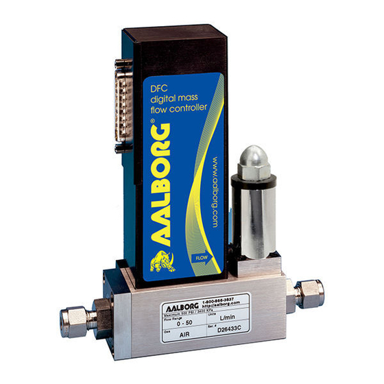
DFC MASS FLOW CONTROLLER
aalborg
7
=
=
=
20 CORPORATE DRIVE
ORANGEBURG, NY 10962
PHONE: 845.770.3000
FAX: 845.770.3010
=
=
e-mail: info@aalborg.com
toll free in usa or canada: 1.800.866.3837
web site: www.aalborg.com
Advertisement
Table of Contents
Troubleshooting

Related Manuals for Aalborg DFC

Summary of Contents for Aalborg DFC
- Page 1 Technical Data Sheet No. TD9805M Rev. O Date of Issue: February 2012 OPERATING MANUAL DFC MASS FLOW CONTROLLER aalborg 20 CORPORATE DRIVE ORANGEBURG, NY 10962 PHONE: 845.770.3000 FAX: 845.770.3010 e-mail: info@aalborg.com toll free in usa or canada: 1.800.866.3837 web site: www.aalborg.com...
- Page 2 CAUTION: This product is not intended to be used in life support applications! CAUTION: K-Factors at best are only an approximation. K-Factors should not be used in applications that require accuracy better than +/- 5 to 10%.
-
Page 3: Table Of Contents
TABLE OF CONTENTS 1. UNPACKING THE DFC MASS FLOW CONTROLLER......1.1 Inspect Package for External Damage..........1.2 Unpack the Mass Flow Controller............1.3 Returning Merchandise for Repair............. 2. INSTALLATION..............2.1 Primary Gas Connections..............2.2 Electrical Connections..............2.3 Communication Parameters and Connections........ - Page 4 APPENDIX 1 COMPONENT DIAGRAM............APPENDIX 2 GAS FACTOR TABLE ("K" FACTORS)........APPENDIX 3 DIMENSIONAL DRAWINGS..........APPENDIX 4 SENDING COMMANDS TO THE DFC........APPENDIX 5 SDPROC TABLES: GAS INDEPENDENT VARIABLES....GAS DEPENDENT VARIABLES....APPENDIX 6 WARRANTY................
-
Page 5: Unpacking The Dfc Mass Flow Controller
INSTALLATION Primary Gas Connections Please note that the DFC Mass Flow Controller will not operate with liquids. Only clean gases are allowed to be introduced into the instrument. If gases are con- taminated they must be filtered to prevent the introduction of impediments into the sensor. -
Page 6: Electrical Connections
Flow Controller must be horizontal within those stated limits. Should there be need for a different orientation of the meter, re-calibration may be neces- sary. It is also preferable to install the DFC transducer in a stable environment, free of frequent and sudden temperature changes, high moisture, and drafts. - Page 7 RS-485 option: The RS485 converter/adapter has to be configured for: multidrop, 2 wire, half duplex mode. The transmitter circuit has to be enabled by TD or RTS (depending on which is available on the converter/adapter). Settings for the receiver circuit usually should follow the selection made for the transmitter circuit in order to eliminate Echo.
- Page 8 FIGURE b-1, WIRING DIAGRAM FOR DFC TRANSDUCERS.
- Page 9 Cable length may not exceed 9.5 feet (3 meters). Use of the DFC flow transducer in a manner other than that specified in this manu- al or in writing from Aalborg7, may impair the protection provided by the equipment.
-
Page 10: Principle Of Operation
Additionally, DFC model Mass Flow Controllers incorporate a microprocessor and non-volatile memory that stores all calibration factors and directly controls a pro- portionating solenoid valve. The digital closed loop control system of the DFC con- tinuously compares the mass flow output with the selected flow rate. Deviations from the set point are corrected by compensating valve adjustments, thus main- taining the desired flow parameters with a high degree of accuracy. -
Page 11: Dfc 26/36/46 Mass Flow Controllers
Contact your distributor or Aalborg 7 for optional RS232 or IEEE488 interfaces. COMMAND SIGNAL: 0-5 VDC (200K Ω input impedance); 4-20 mA optional. TRANSDUCER INPUT POWER: DFC - +15 +5% VDC, 450 mA max, 6.75 watts max; -15 +5% VDC, 450 mA max; 6.75 watts max;... -
Page 12: Ce Compliance
[Cable length may not exceed 9.5 feet (3 meters)]. FREE PC SOFTWARE WITH GAS BLENDING AND PROGRAMMABLE FLOW FUNCTIONS. CE Compliance Any model DFC bearing a CE marking on it, is in compliance with the below stated test standards currently accepted. EMC Compliance with 89/336/EEC as amended;... - Page 13 FLOW RANGES TABLE I DFC 26 LOW FLOW MASS FLOW CONTROLLERS* CODE scc/min [N std liters/min [N CODE 0 to 10 0 to 1 0 to 20 0 to 2 0 to 50 0 to 5 0 to 10 0 to 100...
- Page 14 3740 5440 8.00 7480 11.00 DFC 46 12850 18.89 1302 TABLE V APPROXIMATE WEIGHTS MODEL WEIGHT SHIPPING WEIGHT DFC 26 transmitter 2.20 lbs (1.00 kg) 3.70 lbs (1.68 kg) DFC 36/46 transmitter 2.84 lbs (1.29 kg) 4.34 lbs (1.97 kg)
-
Page 15: Operating Instructions
Command Module). Allow the Mass Flow Meter or Controller to warm-up for a minimum of 15 minutes. During initial powering of the DFC transducer, the flow output signal will be indi- cating a higher than usual output. This is indication that the DFC transducer has not yet attained it's minimum operating temperature. -
Page 16: Set Point Reference Signal
Set Point Reference Signal DFC flow controllers have a built-in solenoid valve and allow the user to set the flow to any desired flow rate within the range of the particular model installed. This valve is normally closed when no power is applied. -
Page 17: Analog Interface Configuration
Analog Interface Configuration The DFC can be configured for the desired range and scaling by selection of analog board (see APPENDIX 1 on page 21) jumpers as follows: 0 to 5 V output: Jumper pins 2 and 3 of JP6. -
Page 18: Flow Path Cleaning
The particular RFE used in a given Mass Flow Controller depends on the gas and flow range of the instrument. 6.2.2 DFC 26 models Unscrew the inlet compression fitting of meter. Note that the Restrictor Flow Element (RFE) is connected to the inlet fitting. -
Page 19: Valve Maintenance
Contact your distributor or Aalborg7 for optional sealing materials available. Set the DFC into PURGE mode, and attempt to flush through with a clean, fil- tered, and neutral gas such as nitrogen. [Another option for fully opening the valve is to remove the plastic cap on top of the valve, and turn the set screw counter- clockwise until it stops. -
Page 20: Calibration Of Dfc Mass Flow Controllers
F (21.1EC), 20 psig (1.4 bars) [25 psig (1.7 bars) for DFC46] inlet pres- sure and 0 psig (0 bar) outlet pressure. It is best to calibrate the DFC transducers to actual operating conditions. Specific gas calibrations of non-toxic and non-cor- rosive gases are available at specific conditions. -
Page 21: Troubleshooting
TROUBLESHOOTING Common Conditions Your Mass Flow Controller was thoroughly checked at numerous quality control points during and after manufacturing and assembly operations. It was calibrat- ed in accordance to your desired flow and pressure conditions for a given gas or a mixture of gases. -
Page 22: Troubleshooting Guide
Remedy power supply off check connection of power supply lack of reading or output fuse blown disconnect DFC transducer from power (DFC) supply; remove the shorting condition or check polarities; fuse resets automatically fuse blown disconnect power cord from AC (SDPROC) supply;... - Page 23 (relative to the sensor tube) DFC valve incorrect valve adjustment re-adjust valve (section 6.2.4) does not work in open pc board defect...
-
Page 24: Calibration Conversions From Reference Gases
CALIBRATION CONVERSIONS FROM REFERENCE GASES The calibration conversion incorporates the K factor. The K factor is derived from gas density and coefficient of specific heat. For diatomic gases: d X C where d = gas density (gram/liter) = coefficient of specific heat (cal/gram) Note in the above relationship that d and C are usually chosen at standard con- ditions of one atmosphere and 25... -
Page 25: Appendix 1 Component Diagram
APPENDIX 1 COMPONENTS DIAGRAMS DFC Digital PC Board (Primary Side) - Page 26 APPENDIX 1 (CONTINUED) DFC Digital PC Board (Secondary Side)
- Page 27 APPENDIX 1 (CONTINUED) DFC Analog PC Board (Primary Side)
- Page 28 APPENDIX 1 (CONTINUED) DFC Analog PC Board (Secondary Side)
-
Page 29: Appendix 2 Gas Factor Table ("K" Factors)
APPENDIX 2 GAS FACTOR TABLES (“K” FACTORS) CAUTION: K-Factors at best are only an approximation. K factors should not be used in applications that require accuracy better than +/- 5 to 10%. K FACTOR Density ACTUAL GAS Relative to N [Cal/g] [g/I] Acetylene C... - Page 30 K FACTOR Density ACTUAL GAS Relative to N [Cal/g] [g/I] Deuterium D 1.00 1.722 1.799 Diborane B .4357 .508 1.235 Dibromodifluoromethane CBr .1947 9.362 Dichlorodifluoromethane (Freon-12) CCl .3538 .1432 5.395 Dichlofluoromethane (Freon-21) CHCl .4252 .140 4.592 Dichloromethylsilane (CH SiCl .2522 .1882 5.758 Dichlorosilane SiH...
- Page 31 K FACTOR Density ACTUAL GAS Relative to N [Cal/g] [g/I] 1.000 .0861 3.610 Hydrogen Bromide HBr 1.000 .1912 1.627 Hydrogen Chloride HCl .764 .3171 1.206 Hydrogen Cyanide HCN .9998 .3479 .893 Hydrogen Fluoride HF Hydrogen Iodide HI .9987 .0545 5.707 Hydrogen Selenide H .7893 .1025...
- Page 32 K FACTOR Density ACTUAL GAS Relative to N [Cal/g] [g/I] Phosphorous Oxychloride POCl .1324 6.843 Phosphorous Pentafluoride PH .3021 .1610 5.620 Phosphorous Trichloride PCl .1250 6.127 Propane C .399 1.967 Propylene C .366 1.877 Silane SiH .5982 .3189 1.433 Silicon Tetrachloride SiCl .284 .1270 7.580...
-
Page 33: Appendix 3 Dimensional Drawings
APPENDIX 3 DIMENSIONAL DRAWINGS DFC 26 Mass Flow Controller NOTES: Aalborg7 reserves the right to change designs and dimensions at its sole discretion at any time without notice. For certified dimensions please contact Aalborg7. - Page 34 DFC 36/46 Mass Flow Controller NOTES: Aalborg7 reserves the right to change designs and dimensions at its sole discretion at any time without notice. For certified dimensions please contact Aalborg7.
-
Page 35: Appendix 4 Sending Commands To The Dfc
Carriage return character. Default address for all units is 11. Several examples of commands follow. All assume that the DFC has been configured for address 15 (0F hex) on the RS485 bus: To put the unit in digital mode: !0F,M,D<CR>... -
Page 41: Appendix 5 Sdproc Tables: Gas Independent Variables
APPENDIX 5 CALIBRATION TABLE: GAS INDEPENDENT VARIABLES DATA INDEX NAME NOTES TYPE BlankSDPROC char[10] Do not modify. For internal use only. SerialNumber char[20] ModelNumber char[20] SoftwareVer char[10] TimeSinceCalHr float Time since last calibration in hours. Options uint Misc. Options. AOutOffset_mA AddressRS485 char[3] Two character address for RS485 only. - Page 42 DATA INDEX NAME NOTES TYPE Kgain[2] float Kgain[3] float Kgain[4] float Kgain[5] float Reserved float Reserved float Reserved float Reserved float Reserved float Reserved float ValveTbl[0][open] float Index 0: Valve actuation. Must be 0.0.- Do Not Alter ValveTbl[0][valve value] uint Index 0: Valve: D/A value - Do Not Alter ValveTbl[1][flow] float...
-
Page 43: Gas Dependent Variables
CALIBRATION TABLE: GAS DEPENDENT VARIABLES DATA INDEX NAME NOTES TYPE GasIdentifer char[27] FullScaleRange float StdTemp float StdPressure float StdDensity float CalibrationGas char[27] CalibratedBy char[20] CalibratedAt char[20] DateCalibrated char[10] DateCalibrationDue char[10] PID_Kp float PID_Ki float PID_Kd float SensorTbl[0][Sensor Value] uint Index 0: Must be 120 (zero value) SensorTbl[0][Flow] float Index 0: Must be 0.0 (zero PFS) - Page 44 DATA INDEX NAME NOTES TYPE SensorTbl[8][Sensor Value] uint SensorTbl[8][Flow] float SensorTbl[9][Sensor Value] uint SensorTbl[9][Flow] float 133 SensorTbl[10][Sensor Value] uint SensorTbl[10][Flow] float Flow in PFS. Should be 1.0 Note: Values will be available for selected gas only.
-
Page 45: Appendix 6 Warranty
APPENDIX 6 WARRANTY Aalborg7 Mass Flow Systems are warranted against parts and workmanship for a period of one year from the date of purchase. Calibrations are warrant- ed for up to six months after date of purchase, provided calibration seals have not been tampered with. - Page 46 TRADEMARKS Aalborg7 is a registered trademark of Aalborg7 Instruments. VCR7 is a registered trademark of Swagelok Marketing Co. Viton7 is a registered trademark of Dupont Dow Elastometers L.L.C. Buna7 is a registered trademark of DuPont Dow Elastometers. Kalrez7 is a registered trademark of DuPont Dow Elastomers.
- Page 47 Website: www.analyt-mtc.de e-mail: ANALYT_MTC@T-online.de e-mail: info@analyt-mtc.de AALBORG 7 a registered trademark of Aalborg Instruments and Controls, Inc. Aalborg reserves the right to make changes to information and specifications in this manual without notice. © Copyright 2001 Aalborg Instruments. All rights reserved.
- Page 48 Products Manufactured By Aalborg ROTAMETERS Single Tube Aluminum / Brass / Stainless = Interchangeable Glass Flow Tubes = Optional Valves Multiple Tube Two to Six Channels = Aluminum or Stainless PTFE Single and Multiple Tube Chemically Inert = 1 to 4 Channels = Interchangeable Glass Flow tubes...
Need help?
Do you have a question about the DFC and is the answer not in the manual?
Questions and answers