Table of Contents

Subscribe to Our Youtube Channel
Related Manuals for Schiedel Prima Plus

Summary of Contents for Schiedel Prima Plus
- Page 1 SCHIEDEL INSTALLER REWARDS Prima Plus Installation Instructions DON'T FORGET TO REGISTER YOUR INSTALLATIONS AND START EARNING SCHIEDEL INSTALLER REWARDS See inside for more details www.schiedel.com/uk SAP Issue 2 | 940003422 | April 2019...
-
Page 2: Table Of Contents
The Prima Plus range is manufactured under the strict requirements • When The product is used on solid fuel applications of BS EN ISO 9001 Quality management scheme. Prima Plus has • corrosion certification from Gastec, MPA and TÜV. Prima Plus is Ø100 = 375mm Ø130 = 390mm... -
Page 3: Design Guide
Design Guide MANDATORY REQUIREMENTS Connection to an appliance which is not connected to the fuel supply, should be carried out by a competent person. We recommend the use of HETAS approved installers for solid fuel applications. If installation is carried out by a non HETAS registered installer, the installation must be certified by a local Building Control inspector. -
Page 4: Prior To Installation
Prior to Installation APPLICATIONS Prima Plus is designed for use on solid fuel, gas and oil burning appliances with continuous operating temperatures of up to 600°C. With the addition of a lip seal gasket to the joint, Prima Plus may be adapted for use on condensing gas and oil appliances with positive pressure of up to 200Pa and continuous operating temperatures of up to 200°C. -
Page 5: Connecting Flue Pipe
Connecting Flue Pipe APPLIANCE/CHIMNEY CONNECTION On solid fuel, wood burning or biomass applications requiring a T600 rating, when a single wall connecting flue pipe is used to connect an appliance to a Twin Wall Insulated System Chimney, the lower end of the insulated chimney section must extend a minimum of 425mm below the ceiling. -
Page 6: Connecting Flue Pipe Route
Connecting Flue Pipe CONNECTING FLUE PIPE ROUTE Single wall connecting flue pipes should only be used to connect appliances to a Chimney. They should not pass through any roof space, partition, internal wall or floor, except to pass directly into a chimney through a wall of the chimney. Connecting flue pipes should be located as to avoid igniting combustible material. -
Page 7: Bs En 15287-1
BS EN 15287-1 Acceptable alternative Methods of connection Where a horizontal connecting flue of more than 150mm is required to connect a solid fuel fired appliance to a chimney, an installation method as per the examples below may be used provided the following criteria is met:- The maximum length of horizontal connecting flue pipe does not exceed 450mm;... -
Page 8: Installation Instructions
With the exception of the direct connection to the appliance, there is no requirement to apply sealant to the joints of the Prima Plus system. CONNECTING TO AN APPLIANCE The male spigot is pushed inside the appliance outlet. The joint should then be sealed to suit each application. - Page 9 PRIMA PLUS Prima Plus is converted for use on positive pressure condensing systems systems by adding a lip seal gasket into the inward bead on the male spigot of the standard components, which are approved as being suitable for use in condensing applications with a P1 designation.
- Page 10 ADAPTOR FROM PRIMA PLUS TO ICS This component is used to convert from Prima Plus to the ICS System Chimney. The protruding liner of the ICS should be pushed down inside the female socket of the Prima Plus.
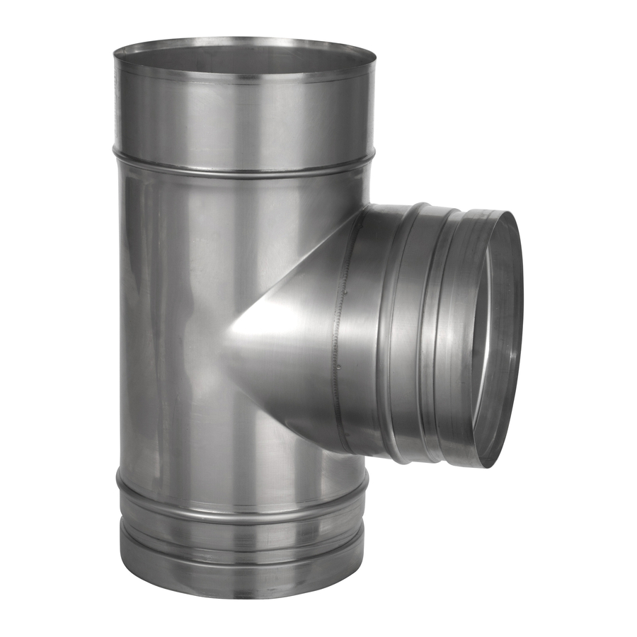
- Page 11 Installation Instructions 90˚ TEE This component may be used to connect from a connecting flue pipe to the vertical system chimney at 90° or the branch may be used to locate a draft stabiliser. It is installed as per a standard pipe section.
- Page 12 Fig. 1 2 PIECE TRIM COLLARS (90° & 45° VARIANTS) Trim 2 piece trim collars are fitted around the Prima Plus pipe where it Collar protrudes through the wall (see Fig. 1). They should be fastened to the wall using an adequate method of fixing.
- Page 13 Chimney Lining Components Note: It is mandatory that when using Prima Plus as chimney liner, the liner MUST NOT be supported at the top of the stack. See components below. LOWERING PIPE The lowering pipe is used to take the weight of up to 15 x 1m pipe lengths as they are lowered down the existing chimney stack.
- Page 14 Chimney Lining Components CEILING HANGER This accessory is designed to support horizontal runs of the chimney from the roof or ceiling and offers adjustment from 130mm to 1115mm. Once the position of the ceiling support has been determined, the section length of uni-rax channel must be securely fixed to the roof or the ceiling using a method of attachment to ensure adequate attachment and support.
- Page 15 Chimney Lining Components Cantilever Support Adjustment Dimention Table Int Ø C max Type 325 Type 457 Type 570 C min Type 325 Type 457 Type 570 Type 570 EXPANSION JOINT The expansion joint must be used at the top of the masonry stack to close off the stack and to allow for thermal expansion within the chimney system.
- Page 16 CONNECTING TERMINALS TO EXPANSION JOINT The male spigot is pushed down inside the female form of the expansion joint, which incorporates the standard Prima Plus female form. The joint is then secured using a Prima Plus standard locking band, which is purchased separately.
- Page 17 Chimney Lining Components ELBOWS 15° - 90°AND ADJUSTABLE INSPECTION ELBOW All Elbows provide a change of direction form the vertical. For offset information on standard elbows, please refer to tables on page 13. 87˚ FIXED BEND For use on condensing systems allowing 3° incline. 0 - 90˚...
- Page 18 Offset Dimensions (Made By Assembling 2 Bends and a standard pipe section) 15˚ Offset with standard Pipe lengths Ømm Effec- tive 1136 1140 1143 1154 1161 1165 1173 1179 1191 Pipe Effec- tive Pipe Effec- tive Pipe 30˚ Offset with standard Pipe lengths Ømm Effec- tive...
- Page 19 Typical Installation SYSTEM CHIMNEY ON INDUSTRIAL SPACE HEATER Anti-Splash Terminal CHIMNEY LINER ON INSET FIRE 1000mm Pipe 200mm Pipe Adjustable Pipe Storm Collar 200mm Pipe Raincap & Locking Wall Support Band Top Plate 90˚ Tee Expansion Joint End Cap with Drain Adjustable Pipe 200mm Pipe Appliance...
- Page 20 Typical Installation CONNECTING FLUE PIPE & SYSTEM CHIMNEY ON COMMERCIAL CASCADE SYSTEM WITH CONDENSING APPLIANCES Raincap without Mesh Flat Flashing c/w Storm Collar 1000mm Pipe 300mm Pipe 1000mm Pipe 93˚ Tee Wall Support Adjustable Pipe 93˚ Reducing Tee Tee Cap with Drain 200mm Pipe 1000mm Pipe...
- Page 21 Max Offset Info (In Same Plane) 125-200 Int Ø X (m) Y (m) max length 1800mm min height before 1st offset 600mm Component Weights Approximate Weights of Finished Goods(Kg) Internal Diameter Length(mm) 1000 1.22 0.61 0.30 1.52 0.76 0.38 1.88 0.99 0.49 2.28...
- Page 22 Mechanical sweeping methods such as Rodtech, Rodstation and Gardus, which have been tested and approved by Schiedel Chimney Systems may be used. Cleaning/inspection of any chimney system should be carried out at least once a year, along with maintenance of the...
- Page 23 In the event of a fault developing in the product due to defective materials or faulty manufacture Schiedel Chimney Systems undertake to replace the product only. Schiedel Chimney Systems cannot accept liability nor take any responsibility for the installation, building or redecorating costs or any other consequential losses arising.
- Page 24 The Schiedel Installation App Download the app today, as it offers a number of very useful guides on all aspects of installing an appliance using Schiedel Chimney Systems, including: • Quick and straightforward reference for installers. • Video breakdowns of each stage of the installation process, from connection to the appliance through to termination.
Need help?
Do you have a question about the Prima Plus and is the answer not in the manual?
Questions and answers