Table of Contents
Advertisement
Quick Links
Advertisement
Table of Contents

Related Manuals for JIB DP25016B

Summary of Contents for JIB DP25016B
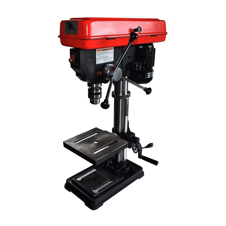
- Page 1 MODEL DP25016B FOR YOUR SAFETY: READ ALL INSTRUCTIONS CAREFULLY...
-
Page 2: General Safety Instructions For Power Tools
Table of Contents General safety instructions for Power Tools Main specification Unpacking and checking contents List of loose parts in the box and bags Getting to know your drill press Assembly Lubrication Maintenance Wire diagram Trouble shooting Repair parts General safety instructions for Power Tools 1.KNOW YOUR POWER TOOL Read and understand the ower's manual and labels affixed to the tool.Learn its application and limitations as well as the specific potential hazards peculiar to this tool. -
Page 3: Main Specification
Main Specification Drill Capacity 16 mm / 5/8 in. Chuck Capacity 16 mm / 5/8 in. Swing 250 mm / 10 in. Spindle Taper Spindle Travel 60 mm / 2-23/64 in. Column Diameter 59.5 mm / 2-11/32 in. Motor 120V/1ph/400W Rack &... - Page 5 0-15/64 in.
- Page 6 List of Loose Parts in the box and bags...
-
Page 7: Getting To Know Your Drill Press
Getting to know your drill press - 4-... - Page 8 Assembly Refer to the figure install all parts correctly, tighten the screw and bolts securelly 1 Base 2. Column/w Support Asm 3 M10*1.5-40Screw (4) 4 Head Asm 5 Table 6 Feed Handle 7 Clamp-Column Lock 8 Crank - 5-...
-
Page 9: Maintenance
Lubrication All of the BALL BEARING are packed with grease at the factory.They require no further lubrication. Periodically lubricate the table elevation machanism,the SPLINES (grooves) in the spindle,and the RACK (teeth of the quill),see "Getting to know your drill press." Maintenance Frequently blow out any dust that may accumulate inside the motor. -
Page 10: Troubleshooting
Trouble Shooting TROUBLE PROBABALE CAUSE REMEDY 1.Incorrect belt tension. 1.Adjust tension. 2.Dry Spindle. 2.Lubricate spindle. Noisy Operation 3.Checking tightness of retaining nut on 3.Loose spindle pulley pulley,and tighten if necessary. 4.Loose motor pulley 4.Tighten setscrews in pulleys. 1.Incorrect speed. 1.Change speed. 2.Chips not coming out of hole. -
Page 11: Repair Parts
Repair Parts FIGURE1 FIGURE1 PARTS LIST Description Description Knob 14 Bushing-Rubber Screw-Pan Hd.M5*0.8-12 15 Ring-Retaining Pulley-Motor 16 *Bearing-Ball 17mm Screw-Hex Soc.Set M6*1.0-10 17 Spacer Guard Pulley w/Lables 18 Insert Pulley (includes Key *Bearing-Ball 12mm #15&20) Shaft-Spindle 19 Pulley-Spindle Chuck 20 Nut-Pulley Key-Chuck 21 Belt-"V"5/16*31 10 Tube-Quill... - Page 12 Repair Parts FIGURE2 FIGURE2 PARTS LIST Description Description Head w/Pointer&Trim 21 *Lockwasher-Ext.5mm Motor 22 Screw-Pan Hd.M5*0.8-8 *Nut-Hex M8 23 Screw-Pan Hd.M5*0.8-12 *Washer M8*16*1.6 24 Switch Locking Cord-Motor 25 Key-Switch *Nut-Hex M10 26 Screw-Self Tap.Pan Hd *Lockwasher M10 M4.2*1.4-9.5 Bracket-Motor 27 Cover-Switch Plate Screw-Hex Hd.M8*1.25-20 28 Box-Switch 10 Support-Motor Bracket...
- Page 13 Repair Parts FIGURE3 FIGURE3 PARTS LIST Key No. Description Support-Table w/Scale Support-Lock Handle Tube/Support Base Screw-Hex Hd.M8*1.25-20 Screw-Hex Hd.1/2-12*7/8 Table -10-...
Need help?
Do you have a question about the DP25016B and is the answer not in the manual?
Questions and answers