
Related Manuals for Austria Email WPA 303 E-LF

Summary of Contents for Austria Email WPA 303 E-LF
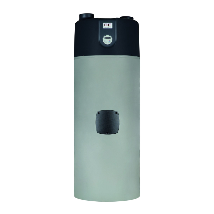
- Page 1 Instructions for Use and Installation Domestic Hot Water Heat Pump WPA 303 E-LF These instructions must be handed over to the end user.
- Page 2 This text is protected by copyright. Any use outside limits of the copyright act without the consent of Austria Email AG is illegal and punishable by law. With this all previous version are invalid. We reserve the right to change the text.
-
Page 3: Table Of Contents
© Austria Email AG Table of Contents Table of Contents ........................2 Introduction ..........................4 Symbols ..........................4 General ..........................5 2.2.1 Obligation of the Manufacturer ................5 2.2.2 Customer Support - Service ..................5 2.2.3 Obligation of the Installer ..................5 2.2.4... - Page 4 © Austria Email AG Installation ........................18 5.5.1 Hydraulic Connection ....................18 5.5.2 Connection of the Air Duct System ................. 19 5.5.3 Connection of Condensate Discharge ..............20 5.5.4 Connection of the Secondary Source ..............22 5.5.5 Electrical Connection ....................24 Heat Pump Start-up ........................
-
Page 5: Introduction
© Austria Email AG Introduction First, we would like to thank you for your trust, which you showed by purchasing our product and we firmly believe that the appliance will serve you well. Prior to initial use, carefully read the contents of the following instructions for safe usage and maintenance and familiarize yourself with the purpose, functionality and methods of handling with the appliance. -
Page 6: General
False and/or insufficient maintenance of the appliance. Disregard of the installation instructions. 2.2.2 Customer Support - Service Customer support and service during warranty period is guaranteed by Austria Email AG. When ordering spare parts for this device, please provide the following: •... -
Page 7: Obligation Of The User
© Austria Email AG Explanation of the entire system’s operation. The fitter must remind the user to carry out regular maintenance works on the appliance to ensure its proper functioning throughout the entire life-span. All maintenance works must be written down in a service record at the end of this instruction manual. -
Page 8: Safety Advice And Recommendations
© Austria Email AG water-tightness air-tightness electrical safety functionality Safety Advice and Recommendations Safety Advice The appliance is manufactured in accordance with the current directives and standards, which enables the manufacturer to label the product with the CE sign. In order to maintain safety and functionality of the appliance, there are warning signs and symbols –... -
Page 9: Safety Data Sheet: Refrigerant R134A
© Austria Email AG Safety Data Sheet: Refrigerant R134a 3.3.1 Identification The working fluid in the appliance is hydro fluorocarbon (HFC) 134a. The refrigerant is not toxic, flammable or explosive and is also not harmful for the ozone, but is however heavier than air, which can cause displacement of air from a room. -
Page 10: In Case Of Leakage
© Austria Email AG 1. Appropriate extinguishing agents: The use of fire extinguishing agents is limited according to space and circumstances in which the fire is being extinguished. The refrigerant does not limit any extinguishing agent. 2. Inappropriate extinguishing agents: not recommended. In case of a fire, use an appropriate extinguishing agent. -
Page 11: Directives
© Austria Email AG ATTENTION Disposal must be performed in accordance with the local and national provisions. 3.3.10 Directives Disposal of the refrigerant must be carried out in accordance with Directive 842/2006/EC, as well as other national and local regulations. - Page 12 © Austria Email AG WPA 303 E-LF A [mm] B [mm] C [mm] D [mm] E [mm] F [mm] 1175 G [mm] 1375 H [mm] 1422 I [mm] 1853 Cold water connection 1'' Heating water connection 1'' – return flow Heating water connection 1'' –...
-
Page 13: Component Parts
© Austria Email AG Component Parts Air duct connection Φ150 - inlet Air duct connection Φ150 - outlet Heat pump housing Compressor Evaporator Controller DHW tank Mg. Anode DHW tank coil Condenser Leveling feet M Electric heater DHW heating by means of a heat pump is a very efficient way of hot water supply. A heat pump consists of a heat pump unit (compressor, evaporator, fan, etc.) and a water heater. -
Page 14: Operating Principle
© Austria Email AG Operating Principle 1. Compressor The refrigerant circuit in a heat pump is a closed 2. Condenser system in which the cooling agent R 134a is 3. Filter dryer circulating as the energy carrier. When the 4. Expansion valve pressure and the temperature are low (e.g. - Page 15 © Austria Email AG • protect the evaporator from frosting; if in summertime the heat pump cannot operate due to a low room temperature, the EH switches on, • alternative source; in case of a failure of the heat pump unit.
-
Page 16: Technical Data
© Austria Email AG ATTENTION The heat pump must never be installed in locations, where there may be harmful substances present in the air, which could damage the device (stables, storage rooms for hazardous substances, outdoors, etc.). Technical Data Product Heat pump for DHW heating with air duct. -
Page 17: Installation
© Austria Email AG Installation Scope of Delivery Scope of delivery: 1. Heat pump WPA 230 ECO 2. Instructions for installation and use 3. Levelling feet Storage The appliance must be stored in a dry and clean place. The allowed storage temperature is between 10°C and 45°C, for a short period of time (up to 24 hrs) the temperature can reach up to 55°C. - Page 18 © Austria Email AG Figure 1: Air is supplied from a neighbouring room and discharged back into the same room. Drying of linen. Figure 2: Air supply and discharge take place in the room where the HP is installed. Figure 3: Air is supplied from a neighbouring room and discharged back. Cooling of a storage room.
-
Page 19: Installation
© Austria Email AG Figure 4: Air is supplied from a neighbouring room and discharged into the surroundings. The most frequent air duct system is one, where the air is supplied from spaces with large quantities of waste heat. Heat is extracted from the air, which is then discharged into the surroundings. Air from kitchens, laundry rooms, bathrooms and toilets, etc. -
Page 20: Connection Of The Air Duct System
© Austria Email AG Expansion vessel dimensioning: Safety valve setting [bar] System pressure [bar] Water heater volume [L] Expansion vessel [L] *This is only a recommendation. The exact size of the expansion vessel must be determined by the installer/project designer according to the size of the system to which the vessel will be installed. -
Page 21: Connection Of Condensate Discharge
© Austria Email AG If the heat pump extracts heat from the surrounding air, the room size must be at least 30 m Maximum length of the air ducts: Maximum length of the air ducts Inner diameter 150 mm 10 m... - Page 22 © Austria Email AG Condensate outlet tube must be connected to the device and routed to the sewage or collecting vessel. At the end of the tube a siphon must be made to prevent suction of odours from the drain.
-
Page 23: Connection Of The Secondary Source
© Austria Email AG Levelling of the heat pump ATTENTION Instructions provided in the figures below must be taken into account to ensure a suitable outlet of the condensate water. ° The heat pump must be leaned slightly backwards to ensure an appropriate outlet of the condensate. - Page 24 © Austria Email AG V1.0 1/2021...
-
Page 25: Electrical Connection
© Austria Email AG 5.5.5 Electrical Connection After the heat pump has been connected to the water supply and evacuated, the electrical connection is carried out. ATTENTION The connection cable can only be plugged into a grounded socket (16 A; 230 V a.c.). -
Page 26: Heat Pump Start-Up
© Austria Email AG Electrical connection of the circulation pump and the PV signal. Heat Pump Start-up Filling the System with Water After the heat pump has been appropriately connected to the water supply by a qualified person, the system must be filled with water and thoroughly evacuated. This is carried out by opening all water pipes in the building. -
Page 27: Start-Up
© Austria Email AG The device is fitted with a standard connection cable. Before the start-up the connection cable must be plugged into a socket with a voltage of 230V a.c. After the cable has been plugged in, the starting sequence is shown on the display. The settings are shown one after another. -
Page 28: Settings
© Austria Email AG Settings Description Indicator of operating mode Temperature and parameter display Button for mode selection. Button for manual thermal desinfection and quick heating Thermal desinfection and quick heating indicator - Button for temperature and parameter selection + Button for temperature and parameter selection... - Page 29 © Austria Email AG ☼ not The water in the water tank is heated to the set temperature illuminated by means of an electric heater. Note: the ambient air temperature has no influence on the flashing operation. The heat pump is heating water to the set temperature with ☼...
- Page 30 © Austria Email AG Important: the overheating is carried out with the heat source determined by the selected operational program, e.g. P1 – compressor, P2 – boiler). Note: in case the overheating is not carried out within 12 hours, the function is switched off and normal operation is switched on.
-
Page 31: Dismantling And Removal
© Austria Email AG Operation of the electric --, 1°C to 55°C -- (off) heater due to low water temperature Setting of the time interval of the automatic thermal disinfection/safety heating – anti-legionella protection: to enter the parameter display, we shortly press the simultaneously. -
Page 32: Care And Maintenance
© Austria Email AG Care and Maintenance 8.2.1 Care ATTENTION The surface of the heat pump can be damaged! The use of inappropriate cleaning agents can cause surface damages. Do not use cleaning agents which can damage plastic surfaces. The use of solvents and chlorinated cleaning agents is prohibited. -
Page 33: Error Indication
© Austria Email AG value and the heat pump will restart automatically. If the room temperature is constantly under the set switch-off value, a different installation room should be selected. The room should be ventilated so that the temperature falls below this value and the heat pump will restart automatically. -
Page 34: Warranty, Guarantee And Product Liability
© Austria Email AG 10 Warranty, Guarantee and Product Liability V1.0 1/2021... - Page 35 © Austria Email AG V1.0 1/2021...
Need help?
Do you have a question about the WPA 303 E-LF and is the answer not in the manual?
Questions and answers