
Summary of Contents for Vision Engineering DRV-Z1
- Page 1 User Guide DRV-Z1 Unique ergonomic digital stereo 3D full high definition viewer with zoom FM 557119 Vision Engineering been certified for the quality management system ISO 9001:2015.
- Page 2 NAVIGATION INSTRUCTIONS The symbols in the left-hand margin of each page of the manual will enable you to carry out the following functions: The buttons in text below do not function. They are for illustrative purposes only. Contents Click on this button to display the Contents page. Back one page.
-
Page 3: Table Of Contents
Display head controls Substage illuminator Large base Main menu options Keypad Display settings INTRODUCTION Copyright Camera settings Disclaimer Lighting settings DRV-Z1 General Image saving and source settings System equipment Safety Presets and hotkeys Display head Servicing General settings Zoom module Symbols used... -
Page 4: System Serial Numbers
PREFACE System serial numbers Unit type Serial number Display head Zoom module Stand Substage illuminator Keypad Substage illuminator Display head Stand Keypad Zoom module... -
Page 5: Copyright
Copyright in this document is owned by Vision Engineering Ltd. Any person is hereby authorised to view, copy, print and distribute this document subject to the following ƒ All operators have read, understood and observe the user manual, in particular the conditions: health and safety guidance. -
Page 6: Symbols Used
Compliance statements the electrical input connector is always available. non-compliant use shall invalidate all rights to any Vision Engineering and its products conforms to the warranty claims. ƒ Avoid positioning your system where bright reflections requirements of the EC Directives on Waste Electrical may affect the image. -
Page 7: Unpacking
UNPACKING Display head & mirror Lifting the display head and mirror box is recommended to be a two person operation. Place the box on a solid surface with clear access then open the top of the box and remove the Mirror Pack (see page 12 for Mirror... -
Page 8: Zoom Module
Stand Zoom module Open the top of the box, lift the stand out complete with foam packing. Open the top of the box and remove the top tray containing the remote keypad (see page 16 for attachment details), the foam Remove the foam packing from the cardboard tray and then objective lens holder... -
Page 9: Small Base
Small base Large base Open the front of the box and slide out the short base and its foam Open the front of the box and slide out the large base and its foam packing packing Remove the foam packing and place the base on a bench ready for Remove the foam packing and place the base on a bench ready for assembly to the stand (see page... -
Page 10: Introduction
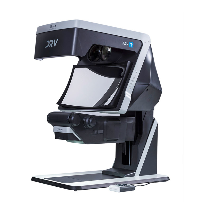
INTRODUCTION DRV-Z1 Short base stand DRV is a unique, advanced, stereo image presentation system designed to provide fully interactive, real time, natural 3D visualisation with outstanding depth perception. System equipment Display head Long base stand Zoom module INTRODUCTION... -
Page 11: Assembly
ASSEMBLY Stand to base attachment Using the Allen key provided, attach the base to the stand using the Place the foam packing saved from the unpacking procedure on four bolts provided. page 7 and place it on a suitable bench. Attach the cover bracket with Lift the stand... -
Page 12: Head Attachment
Head Attachment Front mirror attachment Remove the protective cover and then Ensure the table/bench on which the unit is to be assembled/used is press the sides of the frame as shown suitable for the weight of the complete system. to release its securing clips. Position the stand so the head can be easily attached to it. -
Page 13: Zoom Module Attachment
Zoom module attachment Transit bolt removal Attaching the objective Carefully turn the Zoom Module over, taking care not to touch Wind the coarse focus control to the back end-stop in order to line the mirror. up the access holes for the Allen key. Unscrew and remove the transit bolt Locate the objective in position and lightly tighten the securing screw... -
Page 14: Attaching The Zoom Module
Attaching the zoom module If the location of the unit requires the zoom module to be attached from If required wind the focus control to expose the dovetail and fixing the opposite side of the stand, move the screw on the back of the screw head zoom module as shown. -
Page 15: Operation And Setup
Zoom module connections OPERATION AND SETUP Display head connections Display Head Zoom Module / other HDMI IN Left HDMI Left HDMI IN Right HDMI Right Zoom Module power and control Power and control (USB-C) (USB-C) HDMI OUT Left Slave Display Head HDMI IN Left or external monitor HDMI OUT Right... -
Page 16: Zoom Module Controls
Zoom module controls Display head controls The user controls are to interact with the on-screen menu (see page and adjust the system height: ƒ Select ƒ Up ƒ Down Fine focus ƒ ƒ Left Coarse focus ƒ ƒ Right Zoom ƒ... -
Page 17: Main Menu Options
Main menu options lower the head as required). Remote keypad Both the Display head controls and the remote keypad can be used to access and navigate the menu Connect the remote keypad as shown below: For details regarding Hotkeys and Presets, see page 23). - Page 18 Display settings The following display setting options are available: Contrast This function enables the contrast of both displays to be adjusted. Brightness Use the buttons to highlight the icon and press enable the contrast value to be altered. Contrast Use the buttons to decrease or increase the value (between 0-100) as required.
- Page 19 Camera settings The following camera setting options are available: Exposure time This function enables the shutter speed of the camera to be adjusted. Use the buttons to highlight the icon and press Gain enable the exposure time value to be altered. Exposure time Use the buttons to decrease or increase the value as required.
- Page 20 Contrast Horizontal image mirror This function enables the contrast of the camera to be adjusted. This function mirrors the output image from the cameras horizontally. Use the buttons to highlight the icon and press Use the buttons to highlight the icon and press enable the horizontal mirror image to be set on or off.
- Page 21 Lighting settings Substage illumination This function enables the intensity of the substage to be adjusted. The following lighting setting options are available: Use the buttons to highlight the icon and press enable the substage illumination value (0-25) to be altered. Ringlight illuminator Use the buttons to decrease or increase the value as required.
-
Page 22: Image Saving And Source Settings
Image saving and source settings The following image setting options are available: Save options This function saves the image either as separate PNG files with left and right (L&R) denotation or as a single extended PNG file. Save image Use the buttons to highlight the icon and press Save options... -
Page 23: Presets And Hotkeys
Presets and hotkeys Hot key short press This function loads one of the selected functions (see below) on to the The following preset and hot key options are available: required hot key which will be applied when the hot key (P1-P3) is pressed ƒ... -
Page 24: General Settings
General settings Digital magnification This function turns digital magnification on or off. The following preset and settings options are available: Use the buttons to highlight the icon, press display the options then use the buttons to highlight On or Off as required, press to set the selection and then press to return to the settings menu. - Page 25 Crosshair settings Time settings This function sets the display crosshair options. This function sets the system time. Use the buttons to highlight the icon and press Use the buttons to highlight the icon and press to display the crosshair options. display the time settings.
- Page 26 Transparency System Standby option This function sets the Transparency level of the on-screen menu. This control turns on or off the feature which puts the system into standby after a set time if no input is detected. Use the buttons to highlight the icon and press Use the buttons to highlight the...
-
Page 27: Troubleshooting
TROUBLE SHOOTING Troubleshooting Further head height adjustment Issue Solution Hardware If the up and down head movement (see page 16) needs adjustment, Brake squeaks or does not Brake adjusted between the head proceed as follows: release when brake button and the stand needs turning anti- Adjust the friction control by turning it clockwise to decrease the pressed and head moved. -
Page 28: Technical Data
TECHNICAL DATA Technical data Optical data Field of View Field of View Objective lenses Part Number Optical Magnification range Working distance at minimum mag H/V at maximum mag H/V 0.33x DRV233 6.1x – 61x 182mm 65.5/36.8mm 6.5/3.7mm 0.4x DRV240 7.4x – 74x 138mm 54.0/30.4mm 5.4/3.0mm... -
Page 29: System Weight
System weight System power DRV System Weight Input Output Head weight (no mirror) 17.9kg 100-240V AC 50/60Hz 12V 5A max 60W max Mirror weight 2.1kg This is the maximum power delivered by the unit power supply. Stand weight 11kg Only use with the supplied power supply. Short Base weight Long Base weight Zoom module weight... -
Page 30: Servicing
SERVICING Service record Service Comments Date of service Date of next service Company Signature All product specifications and data are subject to change without notice SERVICING... -
Page 31: Warranty
This product is warranted to be free from defects in material and workmanship for a period of one year from the date of invoice to the original purchaser. If during the warranty period the product is found to be defective, it will be repaired or replaced at facilities of Vision Engineering or elsewhere, all at the option of Vision Engineering. - Page 32 Visit our multi-lingual website: www.visioneng.com Disclaimer – Vision Engineering Ltd. has a policy of continuous development and reserves the right to change or update, without notice, the design, materials or specification of any products, the information contained within this brochure/datasheet and to discontinue production or distribution of any of the...
Need help?
Do you have a question about the DRV-Z1 and is the answer not in the manual?
Questions and answers