Regulus PG500 Installation, Wiring And Operation Instructions
Uninterruptible power supply with thermostat for regulus ctc ecoair heat pump
Hide thumbs
Also See for PG500:
- Installation and operator's manual (10 pages) ,
- Installation, wiring and operation manual (12 pages)

Related Manuals for Regulus PG500

Summary of Contents for Regulus PG500
- Page 1 Installation, Wiring and Operation Instructions UNINTERRUPTIBLE POWER SUPPLY WITH THERMOSTAT FOR REGULUS CTC EcoAir HEAT PUMP v. 1.2...
-
Page 2: Table Of Contents
8 Operation overview ........................7 9 Overview of possible faults and troubleshooting ............8 10 Maintenance ..........................8 Enclosed: Instruction Manual for UPS PG500 Scope of Supply: • Backup power source UPS PG500 • UPS THERMOSTAT with Pt1000 sensor •... -
Page 3: Description
If the temperature at the thermostat sensor drops below 5°C, the UPS THERMOSTAT connects the battery with the UPS unit (PG500) and the circulation pump is started. The pump is kept running until the sensor temperature rises above 6°C. This prevents the water circuit of the heat pump from freezing. -
Page 4: Ups Thermostat Connections
Layout principles: • UPS unit (PG500), UPS THERMOSTAT and battery shall be placed close to one another in such a manner that the prepared length (2m) of 12V cables (2 blue cables and 2 red ones) will be sufficient. -
Page 5: Electric Wiring
. 2. Plug the cable with wall plug into the socket on the UPS (PG500) back side. Wire the live wire from UPS (L-UPS) to the auxiliary relay, contact No. 3. Then wire the neutral lead N-UPS to the pump N clamp (see the wiring diagram). -
Page 6: Temperature Sensor Connection
6 Temperature sensor connection The sensor shall be placed into a heat pump’s heating water sheath. The sheath shall be mounted into the outdoor pipe section, min. 200 mm and no more than 400 mm from the wall. The sheath shall be located downstream the heat pump – see the layout diagram. If the unit cannot be placed in such a way that the supplied 2.5 m cable is enough, the cable may be extended. -
Page 7: Operation Overview
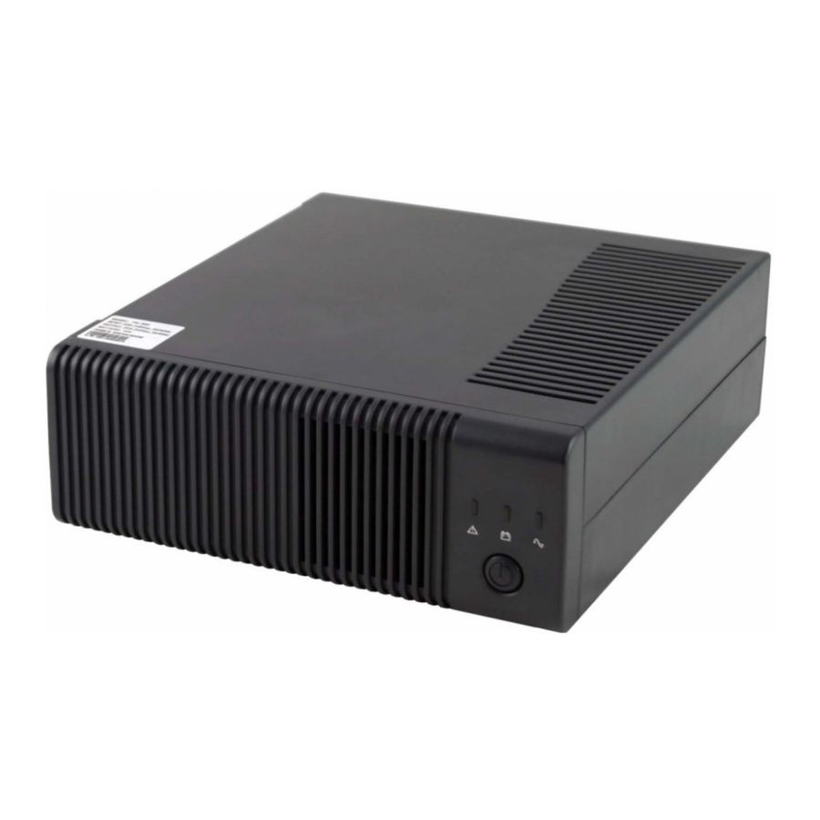
8 Operation overview The meaning of indication LEDs: green - circulation pump running yellow - outdoor piping temperature below +5 °C yellow - outdoor piping temperature below +5 °C red - sensor defect Detailed description of all the states: Sensor Mains Temperat. -
Page 8: Overview Of Possible Faults And Troubleshooting
9 Overview of possible faults and troubleshooting FAULT DESCRIPTION CAUSE TROUBLESHOOTING Green LED is not lit The 230/12V power Check the transformer for outgoing voltage and on the THERMOSTAT supply transformer is not a proper position of the terminal in the unit. but the socket is connected. - Page 9 IMPORTANT INFORMATION ON DISPOSAL IN COMPLIANCE WITH THE EUROPEAN DIRECTIVE 2002/96/ES Do not dispose of this product as unsorted municipal waste. Please dispose of this product by returning it to the point of sale or to your local municipal collection point for recycling. Respecting these rules will help to preserve, protect and improve the quality of the environment, protect human health and utilize natural resources prudently and rationally.
- Page 10 Your claim will be dealt with by your seller at the address shown. Date of Purchase:........Rubber stamp print and signature of the seller: 06/2015 REGULUS spol. s r.o. Do Koutů 1897/3 http://www.regulus.eu 143 00 Praha 4 E-mail: sales@regulus.eu...
Need help?
Do you have a question about the PG500 and is the answer not in the manual?
Questions and answers