
Related Manuals for K-Rain 3208-UWRFS


Summary of Contents for K-Rain 3208-UWRFS
- Page 1 Universal Wireless Rain/Freeze Sensor OWNER’S MANUAL AND INSTALLATION INSTRUCTIONS 3208-UWRFS...
-
Page 2: Table Of Contents
TABLE OF CONTENTS Introduction . . . . . . . . . . . . . . . . . . . . . . . . . . . . . . . . . . . . . . . . . . . . . . . 2 Features &... -
Page 3: Introduction
The Universal Rain Sensor Receiver allows installation with most irrigation controllers – regardless of the manufacturer . Once successfully paired with the K-Rain Wireless Rain/Freeze Sensor, the controller will be able to expertly manage water efficiency by suspending watering during rain and/or freeze periods . -
Page 4: Features & Benefits
. • The K-Rain Wireless Rain/Freeze Sensor (model 3208-UWRFS) can be paired with multiple K-Rain Pro EX 2 .0 Wifi enabled controllers within range, providing additional value for the end user . -
Page 5: Universal Rain Sensor Receiver Components
UNIVERSAL WIRELESS RAIN/FREEZE SENSOR RECEIVER COMPONENTS 1 . Pair Button. Initiates the pairing process . 2. Paired LED. Displays status of pairing to the Wireless Rain Sensor . The LED will flash green for pairing process, stay green under normal conditions and turn flashing red after 24 hours from last successful pairing to indicate connection loss . -
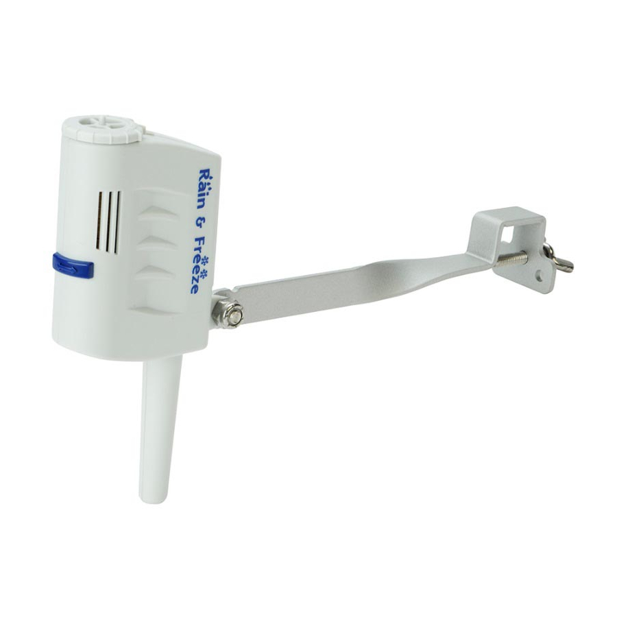
Page 6: Rain/Freeze Sensor Components
RAIN/FREEZE SENSOR COMPONENTS 1. Manual Test Pin. Press and hold for three seconds to confirm proper operation . 2. Vent Adjustment Tab. Used to adjust the dry out time of the sensor . Depending on weather conditions, the farther open the vent windows, the sooner the unit will dry out and let the controller resume normal operations . -
Page 7: Installing The Universal Rain Sensor Receiver Into Controllers
• Controllers with global overide and/or switch must be active/on in order for the sensor to work properly. Installing the K-Rain Universal Rain Sensor Receiver into controllers WITHOUT sensor terminals. a. WITHOUT pump start relay/master valve (Fig. 1). Find the controller common terminal (generally marked “C”... -
Page 8: Wiring For All Installation Methods
b. WITH pump start relay/master valve (Fig. 2). Locate the common wire to the solenoid valves and the common wire lead to the coil of the relay that starts the pump . If these two wires are connected to the “common” terminal on the controller, disconnect both of them . -
Page 9: Mounting The Universal Rain Sensor Receiver
MOUNTING THE UNIVERSAL RAIN SENSOR RECEIVER • Remove the Back Housing from the Main Housing using FIGURE 3: Side Clips the side clips shown here . • Mount the Back Housing through the 3 mounting holes utilizing the supplied hardware (fig .3) . •... -
Page 10: Mounting The Rain Sensor
MOUNTING THE RAIN SENSOR Standard Flat Mounting Mount the sensor on a surface that is unobstructed to rain fall, but away from the path of the sprinkler water spray . Gutter Mounting Allows the rain sensor to be mounted directly to the side of the gutter . Position the gutter mount on the edge of the gutter and twist the thumbscrew to secure it in place . -
Page 11: Adjustments And Operation
ADJUSTMENTS AND OPERATION When the Rain Sensor activates due to sufficient rainfall (after rainfall quantities of 1/8” through 1/2” or more), the sprinkler system will become inactive until the moisture-absorbent discs inside the Rain Sensor have dried out . To adjust to the desired quantity of rainfall, rotate the Rainfall Adjustment Cap on the rain sensor housing to the range desired (See Fig . -
Page 12: Specifications
SPECIFICATIONS Mounting: Supplied screws through Back Housing for standard flat and gutter installation . Rating: 3 amp, 24 V AC, NC (Normally Close contacts) Operating Temperature Range: 14°F to 149°F (-10°C to 65°C) Hardware: Stainless steel Mounting: 2 in 1 bracket for standard flat and gutter installation Sensor Type: Industry-standard hygroscopic disc stack with adjustable rainfall sensitivity Housing: UV-resistant engineered polymer... -
Page 13: Troubleshooting
TROUBLESHOOTING Follow these simple steps before replacing your rain sensor: System will not activate: a . Check to see that the paired Wireless Rain Sensor discs are dry and switch “clicks” on and off freely by pressing the top of the spindle . b . -
Page 14: Fcc Declaration Of Conformity
3208-WRFS Compliance Test Report Number 16FAB01000511 Compliance Test Report Date March 22, 2016 Responsible Party K-Rain Manufacturing Corporation Address 1640 Australian Avenue Riviera Beach, FL 33404 Telephone 561-844-1002 This equipment has been tested and found to comply with the limits for class B digital devices, pursuant to part 15 of the FCC Rules . -
Page 15: Fcc Notice
FCC NOTICE Sensor FCC ID: This device complies with FCC rules Part 15. Operation is subject to the following two conditions: 1 . This device may not cause harmful interference and 2 . This device must accept any interference received, including interference that may cause undesired operation . -
Page 16: Warranty
. Prior to replacement, K-Rain reserves the right to inspect and authorize the defective part or parts; all defective material returns must be authorized in writing by K-Rain . Liability under this warranty is limited solely to the replacement or repair of defective parts .
Need help?
Do you have a question about the 3208-UWRFS and is the answer not in the manual?
Questions and answers