Advertisement
Rain Sensor
Suspends Automatic Irrigation System
Save water and help the environment, suspending your irrigation system on rainy days with any of the
K‐Rain rain sensors.
Owner's Manual and Installation Instructions
3208‐WRFS
Wireless Rain Freeze Sensor
3208‐HRFS
Rain Freeze Sensor
3208‐HRS
Rain Sensor
Advertisement

Related Manuals for K-Rain 3208-WRFS


Summary of Contents for K-Rain 3208-WRFS
- Page 1 Rain Sensor Suspends Automatic Irrigation System Save water and help the environment, suspending your irrigation system on rainy days with any of the K‐Rain rain sensors. Owner’s Manual and Installation Instructions 3208‐WRFS Wireless Rain Freeze Sensor 3208‐HRFS Rain Freeze Sensor 3208‐HRS Rain Sensor ...
-
Page 2: Table Of Contents
Introduction Thank you for selecting a K‐Rain® Rain Sensor. This sensor will do his part for a greener future on generations to come by efficient use of water, providing water conservation, ease of use, and flexibility to your programmable watering system. Save water and help the environment suspending your irrigation system on rainy days. After a set amount of rain has fallen and/or freezing temperatures exist, the sensor will trigger preventing the controller from start irrigation. For units with freeze sensor , they provide peace of mind (when temperature drops below 37°F [3°C]) by interrupting your sprinklers and reduce the hazards of standing water freezing on your driveway, sidewalks, and patios. Once the rain sensor has dried sufficiently, the sensor allows normal sprinkler operation. Works with most new and existing sprinkler systems. This rain sensor will NOT work with open circuit timers. These sensors are designed to operate with 24 V AC power only. Connecting any of these rain sensors to 120 or 240V AC power may result in severe equipment damage. Table of Contents Features ‐‐‐‐‐‐‐‐‐‐‐‐‐‐‐‐‐‐‐‐‐‐‐‐‐‐‐‐‐‐‐‐‐‐‐‐‐‐‐‐‐‐‐‐‐‐‐‐‐‐‐‐‐‐‐‐‐‐‐‐‐‐‐‐‐‐‐‐‐‐‐‐‐‐‐‐‐‐‐‐‐‐‐‐‐ Rain Sensor Components ‐‐‐‐‐‐‐‐‐‐‐‐‐‐‐‐‐‐‐‐‐‐‐‐‐‐‐‐‐‐‐‐‐‐‐‐‐‐‐‐‐‐‐‐‐‐‐‐‐‐‐‐‐‐‐‐‐‐‐‐‐‐‐‐ Installation ‐‐‐‐‐‐‐‐‐‐‐‐‐‐‐‐‐‐‐‐‐‐‐‐‐‐‐‐‐‐‐‐‐‐‐‐‐‐‐‐‐‐‐‐‐‐‐‐‐‐‐‐‐‐‐‐‐‐‐‐‐‐‐‐‐‐‐‐‐‐‐‐‐‐‐‐‐‐‐‐‐‐‐‐‐ Adjustments and Operation ‐‐‐‐‐‐‐‐‐‐‐‐‐‐‐‐‐‐‐‐‐‐‐‐‐‐‐‐‐‐‐‐‐‐‐‐‐‐‐‐‐‐‐‐‐‐‐‐‐‐‐‐‐‐‐‐‐‐‐‐‐‐‐‐ Specifications ‐‐‐‐‐‐‐‐‐‐‐‐‐‐‐‐‐‐‐‐‐‐‐‐‐‐‐‐‐‐‐‐‐‐‐‐‐‐‐‐‐‐‐‐‐‐‐‐‐‐‐‐‐‐‐‐‐‐‐‐‐‐‐‐‐‐‐‐‐‐‐‐‐‐‐‐‐‐‐‐‐‐‐‐‐ FCC Notice ‐‐‐‐‐‐‐‐‐‐‐‐‐‐‐‐‐‐‐‐‐‐‐‐‐‐‐‐‐‐‐‐‐‐‐‐‐‐‐‐‐‐‐‐‐‐‐‐‐‐‐‐‐‐‐‐‐‐‐‐‐‐‐‐‐‐‐‐‐‐‐‐‐‐‐‐‐‐‐‐‐‐‐‐‐ FCC Declaration of Conformity ‐‐‐‐‐‐‐‐‐‐‐‐‐‐‐‐‐‐‐‐‐‐‐‐‐‐‐‐‐‐‐‐‐‐‐‐‐‐‐‐‐‐‐‐‐‐‐‐‐‐‐‐‐‐‐‐‐‐‐‐‐‐‐‐ Notes ‐‐‐‐‐‐‐‐‐‐‐‐‐‐‐‐‐‐‐‐‐‐‐‐‐‐‐‐‐‐‐‐‐‐‐‐‐‐‐‐‐‐‐‐‐‐‐‐‐‐‐‐‐‐‐‐‐‐‐‐‐‐‐‐‐‐‐‐‐‐‐‐‐‐‐‐‐‐‐‐‐‐‐‐‐‐‐‐‐‐‐‐‐‐‐‐ ... -
Page 3: Features
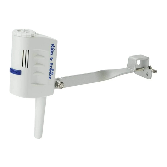
Features Weather resistant. Engineered with UV resistant polymer for outdoor exposure. Maintenance Free. No batteries to replace. Peace of mind for up to ten years Note: Under normal conditions. Unlike other Rain Sensors in the market, our model 3208‐WRFS (K‐Rain wireless rain‐freeze sensor) can be paired with multiple K‐Rain Pro EX Controllers within range, providing additional value for the end user. 2 in 1 Mounting. Provides flexible installation to the user with standard flat and gutter mounting. The models 3208‐WRFS and 3208‐HRFS include a freeze sensor, that prevents the irrigation system from starting when temperatures drop to 37F of below. Quick Installation. Simple, easy and hassle free in all of our models. a. The Wireless Rain‐Freeze Sensor 3208‐WRFS provides the advantage of extremely quick installation and eliminates unsightly wires as no wires installation is needed. Rain Sensor Components 1‐ Manual Test Pin. Press and hold the manual test pin to confirm proper operation. 2‐ Vent Adjustment Tab. Used to adjust the dry out time for the sensor. 3‐ Mounting Arm. Metal extension arm for mounting the sensor. 4‐ Rainfall adjustment Cap. The rain sensor cap can be adjusted to suspend watering, when rainfall amounts of 1/8" (minimum setting) and 1/2" or more has fallen. 5‐ Freeze Sensor (for models 3208‐WRFS and 3208‐HRFS only). Prevents the irrigation system from starting when temperatures drop to 37F of below. When temperatures rise above 37F, the sensor will enable automatic watering. Additional Components of the Wireless Rain‐Freeze Sensor model 3208‐WRFS: ... - Page 4 For model 3208‐WRFS Wireless Rain Freeze Sensor 1. Install the RFM receiver (Model 3206) into your Pro EX Controller. 2. Pair your 3208 Wireless Rain‐Freeze Sensor with the Pro EX Controller. Place dial on pin position. Press UP button until the word “LEARN” is displayed into the LCD. Press the START button, and user will see the word “LEARN” flashing. Press the manual test pin (FOR 3 SECONDS) for the wireless rain sensor to transmit the signal. ...
- Page 5 The controller will display “LEARNED” once the wireless rain sensor has been paired. Press the DOWN button to complete the process. Move the dial back to AUTO. Installation WIRING ‐ For model 3208‐HRFS (Rain Freeze Sensor) or 3208‐HRS (Rain Sensor) IMPORTANT: The rain sensor is sold and designed for 24‐VAC irrigation controllers only. All wiring must ...
- Page 6 Wiring the wired rain sensors into Controllers with Sensor Terminals, simply: Find the controller sensor terminals (generally marked “SENSOR”, “SEN” or “S”) and attach the Rain Sensor control wires directly to these terminals in any order. NOTE: 1. There may be a jumper tab or wire between the sensor terminals that must be removed. 2. If a rain sensor will not be installed, the preinstalled jumper wire must remain installed on the SENSOR terminals. Wiring the wired rain sensors 3208‐HRFS (Rain Freeze Sensor) or 3208‐HRS (Rain Sensor) into ...
- Page 7 A. 24‐VAC Solenoid Valves Only (No Pump Start Relay See Figure 1). With the two wires from the rain sensor at the controller, locate the “common ground” wire of the solenoid valves. If it is connected to the common terminal on the controller disconnect it. Attach one wire of the rain sensor to the “common” terminal (usually marked “COM”) on the controller. Attach the other wire of the rain sensor to the common wire leading to the valves. Note: The common wire to the valves does not have to be interrupted at the controller. The rain sensor may be wired anywhere along the common wire line. Once the rain sensor is mounted, run the wire to the controller, using wire clips every few feet to fasten it. If an extension to the wire provided is needed, use the following table to determine the minimum wire gauge needed: CHECK TO VERIFY CORRECT WIRING Turn on one zone of the sprinkler system that is visible while you are in reach of the rain sensor. Manually depress the manual test pin at the top of the rain sensor until you hear the switch “click” off. The sprinkler zone should stop instantly. If it does not, check wiring for correct installation. Wiring the wired rain sensors 3208‐HRFS (Rain Freeze Sensor) or 3208‐HRS (Rain Sensor) into controllers with pump start/master valve terminal; and no sensor terminals: ...
- Page 8 B. 24‐VAC Solenoid Valves with Pump Start Relay (See Figure 2). Locate the common wire to the solenoid valves and the common wire lead to the coil of the relay that starts the pump. If these two wires are connected to the “common” terminal on the controller, disconnect both of them. Twist these two wires together along with one wire from the rain sensor and secure with a wire nut. Attach the other wire of the rain sensor to the “common” terminal on the controller. Once the rain sensor is mounted, run the wire to the controller, using wire clips every few feet to fasten it. If an extension to the wire provided is needed, use the following table to determine the minimum wire gauge needed: CHECK TO VERIFY CORRECT WIRING Turn on one zone of the sprinkler system that is visible while you are in reach of the rain sensor. Manually depress the manual test pin at the top of the rain sensor until you hear the switch “click” off. The sprinkler zone should stop instantly. If it does not, check wiring for correct installation. Note: The manual activation cycle of some controllers bypasses the sensor inputs. If the Rain Sensor is connected to the sensor terminals, you will need to run an automatic/timed watering program for these types of controllers. Mounting the Rain Sensor Standard Flat Mounting ...
- Page 9 For the wireless model, the signal transmission will be better avoiding interference to the wireless signal. b. Mount in the highest possible position where rain can fall directly upon the rain sensor. c. The rain sensor mounting location will affect the reset rate (amount of time it takes the rain sensor to dry out sufficiently for the sprinkler system to reactivate).
-
Page 10: Adjustments And Operation
ADJUSTMENTS AND OPERATION When the Rain Sensor activates due to sufficient rainfall (after rainfall quantities of 1/8” thru ½” or more), the sprinkler system will become inactive until the moisture‐absorbent discs inside the Rain Sensor have dried out. To adjust it to the desired quantity of rainfall, rotate the cap on the rain sensor housing to adjust the range desired (See Figure 3). Figure 3 The time that it takes the rain sensor to reset for normal sprinkler operation after the rain has stopped is determined by weather conditions (wind, sunlight, humidity, etc.). These conditions will determine how fast the hygroscopic discs will dry out, the same conditions your soil experiences. Note that there is an adjustment capability on the rain sensor that will slow down the reset rate. By turning the “Vent Adjustment Tab” (See Figure 4) to completely or partially cover the ventilation holes, the hygroscopic discs will dry more slowly. This adjustment can compensate for an “overly sunny” installation location or peculiar soil conditions. Experimenting with the vent ring will best determine the ideal vent setting. Figure4 Bypassing the Rain Sensor The Rain Sensor can be temporarily bypassed or deactivated using any one of the following methods: • Use the controller’s sensor bypass switch (if equipped). • Temporarily disconnect the Rain Sensor from the controller’s wiring. ... - Page 11 Note: Always disconnect power to the controller before performing any wiring tasks. Additional Features of the 3208‐WRFS (Wireless Rain Freeze Sensor) ‐ The Pro EX Controller comes from factory as default, with wired rain sensor terminal enabled. Once a wireless rain sensor has been paired with the Pro EX Controller, the terminals for a wired rain sensor becomes disabled. ‐ The Pro EX Controller stores the temperature and date of the last day suspended watering, made by either a rain event or by the freeze sensor (when ambient temp was below freezing point). To display this information, put the controller dial on the REMOTE / PIN location. Press the UP button, until it displays the SENSOR information screen. This screen shows the user the battery % remaining of their wireless rain sensor, and the temperature of the last time the rain sensor was triggered. Note: The user can always change the temperature unit of measurement to Celsius degree by pressing the BACK and NEXT buttons SIMULTANEOUSLY on this screen. To go to the next sensor feature, press the NEXT Button an the screen will display a DATE. Which shows the last day the rain sensor was triggered. The last screen on this sensor section, shows the word “Wired” flashing. ...
- Page 12 This setting is used to deactivate the wireless rain sensor and enabling the rain sensor terminals of the Pro EX controller. In order to do this selection, press the BACK and NEXT buttons SIMULTANEOUSLY until the word WIRED has stopped plashing. ...
-
Page 13: Specifications
SPECIFICATIONS Specifications Mounting: 2 in 1 Bracket for gutter bracket for standard flat and gutter installation Sensor Type: Industry‐standard hygroscopic disc stack with adjustable rainfall sensitivity Rating: 3 amp, 24 V AC, NC (Normally Close contacts) Operating Temperature Range: 14°F to 149°F (‐10°C to 65°C) Hardware: Stainless steel Housing: UV‐resistant engineered polymer Freeze Set Point: 37°F for 3208‐WRFS (Wireless Rain Freeze Sensor) and 3208‐HRFS (Rain Freeze Sensor) Additional Specs for Wireless Version: Rain/Freeze Wireless Range: Up to 400 feet or 120 meters (Line of Sight) * Average Battery Life: is designed to operate up to ten years 10 Years (under normal conditions) Additional Specs for Wired Versions: Control Wire: 25' outdoor‐rated, 2‐wire cable, UL approved TROUBLESHOOTING Follow these simple checks before replacing your rain sensor: System will not come on at all: A. Check to see that the rain sensor discs are dry and switch “clicks” on and off freely by pressing the top of the spindle. B. Look for breaks in the wire leading to the rain sensor and check all wire junctions. C. If the rain sensor is dry and the wire leading to it is good, check the rain sensor switch by nicking the insulation of the two “outer” wires near the unit to expose copper. Turn one sprinkler zone on, and apply a “jumper wire” across the two exposed wires. If the sprinkler now comes on, the switch is bad. Wrap all nicked wires with electrical tape. D. The rain sensor is wired to function with most controllers (normally closed). If you are unable to make the sensor work with the suggestion above you may have a unique controller (normally open). System will not shut off even after heavy rainfall: A. Check wiring for correct installation (See “Adjustments and Operation” section). B. Check sensitivity setting on rain sensor, and move the cap to a more sensitive setting. The rain sensor is an accurate rain gauge and can be verified by setting up a “tube” type rain gauge in the same vicinity and making periodic readings. C. Check for obstructions to rainfall such as overhangs, trees or walls. WARRANTY K‐Rain Manufacturing warrants that its products will be free from materials and workmanship defects for a period of 2 years. With proof of purchase provided, K‐Rain will replace, free of charge, the ... -
Page 14: Fcc Notice
FCC Notice Sensor FCC ID: 2AHQM‐3208WRFS This device complies with FCC rules Part 15. Operation is subject to the following two conditions: 1. This device may not cause harmful interference and 2. This device must accept any interference received, including interference that may cause undesired operation. This equipment has been tested and found to comply with the limits for class B digital devices, pursuant to part 15 of the FCC Rules. These limits are designed to provide reasonable protection against harmful interference in a residential installation. This equipment generates, uses, and can radiate radio frequency energy and if not installed and used in accordance with the instructions, may cause harmful interference to radio communications. However, there is no guarantee that interference will not occur in a particular installation. If this equipment does cause harmful interference to radio or television reception, which can be determined by turning the equipment on and off, the user is encouraged to try to correct the interference by one or more of the following measures: • Reorient or relocate the receiving antenna • Increase the separation between the equipment and the receiver • Connect the equipment to an outlet on a circuit different from that to which the receiver is connected • Consult the dealer or an experienced radio/TV technician for help The user is cautioned that changes and modifications made to the equipment without the approval of the manufacturer could void the user’s authority to operate this equipment. The distance between user and products should be no less than 20cm ... -
Page 15: Fcc Declaration Of Conformity
FCC Declaration of Conformity This equipment has been tested and found to comply with the limits for class B digital devices, pursuant to part 15 of the FCC Rules. These limits are designed to provide reasonable protection against harmful interference in a residential installation. This equipment generates, uses, and can radiate radio frequency energy and if not installed and used in accordance with the instructions, may cause harmful interference to radio communications. However, there is no guarantee that interference will not occur in a particular installation. If this equipment does cause harmful interference to radio or television reception, please refer to you user's manual for instructions on correcting the problem. The undersigned, hereby declare that the equipment specified above conforms to the above requirements. NOTES ...
Need help?
Do you have a question about the 3208-WRFS and is the answer not in the manual?
Questions and answers