Table of Contents
Advertisement
Quick Links
ACCESS MENUS
INSTALLATION AND MAINTENANCE INSTRUCTIONS
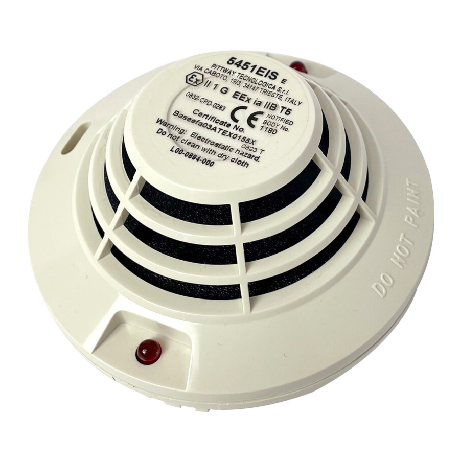
5451EIS Plug-in Intrinsically Safe
Rate-of-rise Thermal Detector with
Fixed Temperature Alarm
Specifications
Diameter:
Height:
Weight:
Input Voltage:
Installation Temperatures:
U.S. –
Europe (Maximum)–
Operating Humidity Range:
Latching Alarm:
Intrinsic Safety Rating:
This sensor must be installed in compliance with the con-
trol panel installation manual and meet the requirements of
the authority having jurisdiction.
NOTICE: This manual should be left with the owner/user
of this equipment.
IMPORTANT: This detector should be cleaned at least once
a year. If cleaning is performed with non-intrinsically safe
equipment, it must be conducted outside the hazardous
area.
General Description
Model 5451EIS is an intrinsically safe rate-of-rise thermal
detector with fixed temperature alarm utilizing a state-of-
the-art dual thermistor sensing circuit. These detectors are
designed to provide open area protection and are to be
used with compatible control panels only. Two LEDs on
each detector light to provide 360° visibility of the detector
indication. Remote LED annunciator capability is provided
as standard.
NOTE: Although the 5451EIS is a UL listed open area heat
detector, UL has not evaluated this product for use
in hazardous environments. The detector is FMRC
and BASEEFA approved for intrinsic safety.
Installation
NOTE: All wiring must conform to applicable installation
codes and regulations.
NOTE: Verify that all detector bases are installed, that the
initiating-device circuits have been tested, and that
the wiring is correct. (Refer to detector base
manual for testing procedure.)
WARNING
Disconnect the power from initiating-device circuits before
installing detectors.
D400-56-00
10.4 cm
5.4 cm
150 g
15 to 28 VDC
32° F to 100ºF (0ºC to 40ºC)
50° C
10% to 93% Relative Humidity (noncondensing)
Reset by momentary power interruption
EEx ia IIC T5
1. Install Detectors:
a. Insert the detector into the detector base.
b. Turn the detector clockwise until the detector drops
into place.
c. Continue turning detector clockwise to lock it in
place.
Tamper-resistance Feature
2. After all detectors have been installed, apply power to
the control unit.
3. Test the detector using the magnet as described under
TESTING.
4. Reset the detector at the system control panel.
5. Notify the proper authorities the system is in operation.
Testing
Before testing, notify the proper authorities that the heat
detector system is undergoing maintenance, and therefore
the system will temporarily be out of service. Disable the
zone or system undergoing maintenance to prevent un-
wanted alarms.
IMPORTANT: If testing is done with non-intrinsically safe
methods, it should be conducted outside the hazardous
area.
Detectors must be tested after installation and periodic
Maintenance. The 5451EIS may be tested as follows:
A. Test Magnet (System Sensor Model No. M02-04)
1
3825 Ohio Avenue, St. Charles, Illinois 60174, USA
1-800-SENSOR2, FAX: 630-377-6495
The detector bases include a feature that, when ac-
tivated, prevents removal of the detector from the
base without the use of a tool. Refer to the instal-
lation instruction manual of the detector base to
make use of this feature.
A Division of Pittway
I56-699-11
Advertisement
Table of Contents

Related Manuals for Pittway SYSTEM SENSOR 5451EIS


Summary of Contents for Pittway SYSTEM SENSOR 5451EIS
- Page 1 ACCESS MENUS INSTALLATION AND MAINTENANCE INSTRUCTIONS 5451EIS Plug-in Intrinsically Safe Rate-of-rise Thermal Detector with A Division of Pittway 3825 Ohio Avenue, St. Charles, Illinois 60174, USA Fixed Temperature Alarm 1-800-SENSOR2, FAX: 630-377-6495 Specifications Diameter: 10.4 cm Height: 5.4 cm Weight:...
- Page 2 ACCESS MENUS 1. Position the magnet against the cover opposite the test module socket. (See Figure 1.) Maintenance 2. The LEDs on the detector should light within 10 sec- The 5451EIS detector has been designed to be as mainte- onds. If the LEDs fail to light, check the power to the nance-free as possible.
- Page 3 ACCESS MENUS INTEGRATION OF THE 5451EIS DETECTORS INTO A SYSTEM SAFE AREA HAZARDOUS AREA (Note 5) Safe area apparatus, which is unspecified except that it must (Note 2) Shunt Zener To next not be supplied from or contain Diode Safety detector(s) under normal or abnormal Barrier or...
- Page 4 ACCESS MENUS FMRC Approved System Diagram INTEGRATION OF THE 5451EIS DETECTORS INTO A SYSTEM SAFE AREA HAZARDOUS AREA (Note 5.) Safe area apparatus, which is To next unspecified except that it must (Note 2.) detector(s) FMRC Entity not be supplied from or contain Approved under normal or abnormal Intrinsic Safety...
Need help?
Do you have a question about the SYSTEM SENSOR 5451EIS and is the answer not in the manual?
Questions and answers