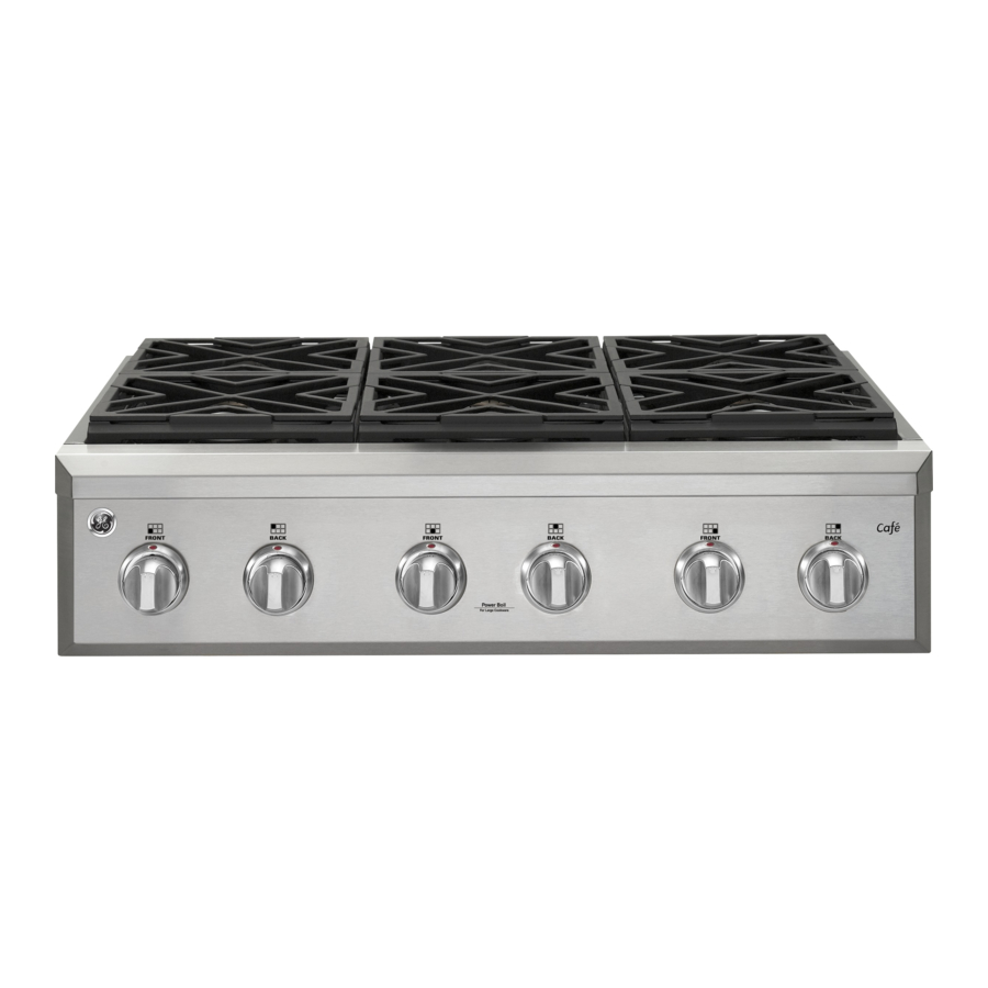
Cafe CGU366 Installation Instructions Manual
Professional rangetop
Hide thumbs
Also See for CGU366:
- Installation instructions manual (56 pages) ,
- Owner's manual (49 pages) ,
- Owner's manual (49 pages)
Table of Contents
Advertisement
Quick Links
Professional Rangetop
CGU366, CGU486
Contents
Safety Information ....................................................... 2
Product Dimensions and Clearances ............................ 4
High Altitude Kit ............................................................. 7
Materials Provided ......................................................... 7
Materials Required (not provided) ................................. 7
Tools Required .............................................................. 7
Remove Packaging ....................................................... 8
Cut the Countertop Opening ......................................... 9
Install Rangetop .......................................................... 10
Gas Supply .................................................................. 11
Electrical Connections ................................................. 12
Check Burners ............................................................. 12
Check Surface Burners ............................................... 12
Finalize Installation ...................................................... 13
When All Hookups Are Completed.............................. 13
Questions? Visit cafeappliances.com.
Installation Instructions
Tools and Materials Required ..................................... 14
Install 12" Backsplash ................................................. 14
Tools and Materials Required ..................................... 15
Install the Wall Support Panels ................................... 15
Install Cover Panels .................................................... 16
English • Français • Español
TM
31-2000816 Rev. 0 11-20 GEA
Advertisement
Table of Contents

Subscribe to Our Youtube Channel
Related Manuals for Cafe CGU366


Summary of Contents for Cafe CGU366
-
Page 1: Table Of Contents
Installation Instructions Professional Rangetop CGU366, CGU486 Contents Safety Information ............2 UX12BS36PSS, UX12BS48PSS Accessory Installation Optional Accessories—12” High Backsplash Design Information Tools and Materials Required ........14 Product Dimensions and Clearances ......4 Install 12” Backsplash ..........14 Installation Information UXADBS36PSS, UXADBS48PSS Accessory Installation High Altitude Kit ............. -
Page 2: Safety Information
Safety Information Have a question or need assistance with your appliance? Try the Café website 24 hours a day, any day of the year! You can also shop for more great Café products and take advantage of all our on-line support services designed for your convenience. - Page 3 Safety Information BEFORE YOU BEGIN IF SOLD OUTSIDE THE U.S. AND CANADA Read these instructions completely and carefully. WARNING IMPORTANT If you wish to use this product with ■ — Save these instructions Liquefied Petroleum (LP) gas containing greater for local inspector’s use. than 10% butane, you must purchase the butane IMPORTANT conversion kit #CXBUPR01 To order, please call ■ —...
-
Page 4: Design Information
Design Information PRODUCT DIMENSIONS AND CLEARANCES FOR 48” MODELS 27-5/8” to Universal Utility Locations Front of 47-7/8” Width Bullnose 2” 8-1/2” Height 17” Locate gas inlet on back 16” wall or on floor 2” from back wall. WARNING Installations without a hood require 48” minimum to combustibles. A custom hood installation with exposed horizontal 48”... - Page 5 Design Information PRODUCT DIMENSIONS AND CLEARANCES FOR 36” MODELS 27-5/8” to Universal Utility Locations 35-7/8” Width Front of Bullnose 2” 17” Locate gas 8-1/2” Height inlet on back 16” wall or on floor 2” from back wall. WARNING Installations without a hood require 48” minimum to combustibles. A custom hood 36”...
- Page 6 Design Information PRODUCT DIMENSIONS AND CLEARANCES 48” and 36” Rangetop Models 29-1/8” To front of control knobs 27-5/8” 1/2” To front of bullnose Countertop level 3/16” † 11/32” 8” Rear finished edge of the Countertop 6-1/2” 1-3/16” control panel Level 8-1/2”...
-
Page 7: Installation Information
Installation Information TOOLS REQUIRED INSTALLATION AT HIGH ALTITUDE Over 6000ft, product configured for natural gas or propane requires installation of kit (WB28X39728 for natural gas and WB28X39729 for propane gas). Drill and Follow the instructions included with the kit. Appropriate Bits Saber Saw MATERIALS PROVIDED Adjustable Wrench Measuring Tape Hold-Down Strap 1/4” Driver or Wrench Regulator Carpenter’s Square MATERIALS REQUIRED (not provided) Safety Glasses Phillips #2 Screwdriver... -
Page 8: Installation
Installation REMOVE PACKAGING ■ C ut the ties holding the grill grate to the grill frame. CAUTION Stand clear. The ends of the cut metal Griddle Flue Cover banding may snap toward you. ■ C ut the metal banding. ■ R emove packaging tape and foam. Dispose of packaging materials properly. ■ R emove grill/griddle covers, grill grate and burner grates. ■ L ift out cast-iron griddle flue cover, grease troughs Grease Troughs and pads. Ties ■ L ift off burner caps and remove foam pad, then lift off burner heads and remove foam pad. -
Page 9: Cut The Countertop Opening
Installation CUT THE COUNTERTOP OPENING 48” wide models are designed to fit in 48” or wider base cabinets 36” wide models are designed to fit in 36” or wider base cabinets Measure carefully when cutting the countertop. Make Cutout Opening with False Bottom sure sides of the opening are parallel. ■ A llow 8” free space below the top surface of the countertop. ■ A llow additional clearances below the burner box to install the regulator and make house supply connections. Use a 90° elbow to route the gas connections and limit interference with drawers or other cabinetry features. ■ T hese rangetops are designed to hang from the countertop by their side flanges. -
Page 10: Install Rangetop
Installation INSTALL RANGETOP CONVERSION TO PROPANE (LP) OR NATURAL GAS ■ S lide the rangetop into the opening. Make sure the rangetop is evenly seated and supported. The pressure regulator and the burner orifices are set for natural gas at the factory. To operate the ■ A hold-down strap with screws is provided to secure rangetop with propane (LP), the regulator and burner the rangetop to the rear or side cabinet walls. -
Page 11: Gas Supply
Installation GAS SUPPLY GAS SUPPLY (cont.) When using pressures greater than 1/2 psig to WARNING Fire Hazard: Do not use a flame to pressure test the gas supply system of the residence, check for gas leaks. disconnect the rangetop and individual shut-off valve from the gas supply piping. When using pressures WARNING Explosion Hazard: Do not exceed of 1/2 psig or less to pressure test the gas supply 25 ft-lbs of torque when making gas line connections. system, simply isolate the rangetop from the gas Overtightening may damage the pressure regulator supply system by closing the individual shut-off valve. -
Page 12: Electrical Connections
Installation ELECTRICAL CONNECTIONS CHECK BURNERS WARNING WARNING Shock Hazard: This appliance must Fire or Explosion Hazard: Do not be properly grounded. Failure to do so can result in operate the burner without all burner parts in place. electric shock. A. Burners - Place surface burners into corresponding Electrical Requirements - 120-volt, 60 Hertz, properly positions on cooktop. grounded dedicated circuit protected by a 15-amp or B. Caps - Place caps on proper size burner. 20-amp circuit breaker or time delay fuse. C. Grates - The left and right grates are NOTE: Use of automatic, wireless, or wired external interchangeable. Place the grates on the cooktop. switches that shut off power to the appliance are not recommended for this product. -
Page 13: Finalize Installation
Installation FINALIZE INSTALLATION WHEN ALL HOOKUPS ARE COMPLETED Place the burner grates over the burners. The grates should be seated and should not rock. Make sure all controls are left in the off position. Make sure the flow of combustion and ventilation air to the The griddle is secured with screws. It is designed to range is unobstructed. be stationary and should not be removed. -
Page 14: Ux12Bs36Pss, Ux12Bs48Pss Accessory Installation
UX12BS36PSS, UX12BS48PSS Accessory Installation OPTIONAL ACCESSORIES—12” HIGH BACKSPLASH INSTALL 12” BACKSPLASH This kit provides for the installation of a 12” high backsplash for 36” Professional Ranges and Rangetops. WARNING This backsplash must be securely fastened to the wall. Failure to do so could result in TOOLS AND MATERIALS REQUIRED damage or personal injury. ■ I nstall and level the range or rangetop and the ■ G loves to protect against sharp edges range hood according to the installation instructions. -
Page 15: Uxadbs36Pss, Uxadbs48Pss Accessory Installation
UXADBS36PSS, UXADBS48PSS Accessory Installation ACCESSORIES—30” TO 36” ADJUSTABLE BACKSPLASH (not included) INSTALL THE WALL SUPPORT PANELS ■ T his backsplash adjusts to fit the space between the top of the range and the bottom of the hood, WARNING from 30” Min. to 36” Max. height. The wall support panels must be securely fastened to the wall. Failure to do so could ■ M aximum shelf load-bearing weight is 40 lbs. result in damage or personal injury. IMPORTANT: This backsplash is designed to cover the wall between the bottom of the hood and the top of TOOLS AND MATERIALS REQUIRED the range. -
Page 16: Install Cover Panels
UXADBS36PSS, UXADBS48PSS Accessory Installation ACCESSORIES—30” TO 36” ADJUSTABLE BACKSPLASH (not included) (Cont.) INSTALL COVER PANELS INSTALL COVER PANELS (cont.) See alternate method if side access is blocked. ALTERNATE METHOD: When side access is blocked ■ H old the bottom cover over the bottom support ■ I nstall bottom cover over the bottom support while while driving one screw (provided) into each side. - Page 17 Notes 31-2000816 Rev. 0...
- Page 18 Notes 31-2000816 Rev. 0...
- Page 19 Notes 31-2000816 Rev. 0...
- Page 20 NOTE: While performing installations described in this book, safety glasses or goggles should be worn. NOTE: Product improvement is a continuing endeavor at GE Appliances. Therefore, materials, appearance and specifications are subject to change without notice. Printed in Mexico 31-2000816 Rev. 0...
Need help?
Do you have a question about the CGU366 and is the answer not in the manual?
Questions and answers