
Related Manuals for CHESTER U.K. Cobra

Summary of Contents for CHESTER U.K. Cobra
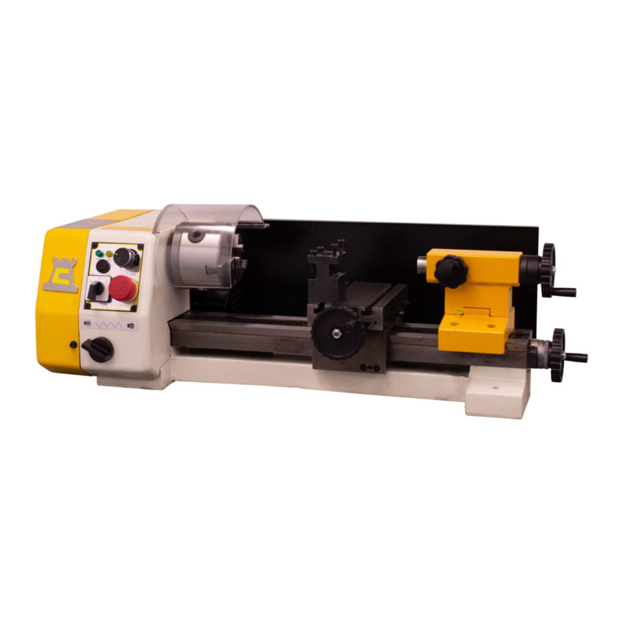
- Page 1 Cobra Lathe Instruction Manual Chester UK Ltd Clwyd Close, Hawarden Industrial Pk Hawarden, Nr Chester Flintshire. CH5 3PZ Tel: 01244 531631 Email: sales@chesteruk.net www.chesteruk.net...
-
Page 2: Table Of Contents
Contents 1. Introduction 2 2. Health & Safety 3 5 3. Machine Specification 6 4. Testing 7 5. Operation 8 16 6. Maintenance 17 7. Oiling Points 18 8. Change Gear Table 19 9. Parts List & Diagrams 20 25 10. Wiring Diagrams 26 27 11. CE Document 28 Chester UK Cobra Lathe ... -
Page 3: Introduction
When buying from Chester you can be assured of a complete backup service with mechanical and electrical engineers that are available to give advice if required. Stock is a large part of any business and Chester have always invested substantially in building a large quantity of machines and spares, ready to satisfy customer requirements. Chester UK has one of the largest stocks of conventional new machines and accessories within Great Britain. Please take time to visit our website: www.chesteruk.net Chester UK Cobra Lathe ... -
Page 4: Health & Safety
8. Always Keep hands and fingers away from any moving parts. 9. Stop The machine before moving chips. 10. Shutoff Power and clean the lathe and work area before leaving the machine. Use of the machine 1. Remove adjusting keys and wrenches Form a habit of checking to see that keys and adjusting wrenches are removed from the tool before turning it ‘on’. 2. Don’t force the tool It will do the job better and be safer at the rate for which it was designed. 3. Use the right tool Don’t force the tool or attachment to do a job for which it was not designed. 4. Secure work Use clamps or a vice to hold work when practical. It’s safer than using your hands, and frees both to operate the machine. Chester UK Cobra Lathe ... - Page 5 A guard or other part that is damaged should be properly repaired or replaced. 3. Disconnect tools Before servicing and when changing accessories such as blades bits, cutters, etc. 4. To prevent The corrosion of machined surfaces when a soluble is used as coolant, pay particular attention to wiping dry the surfaces where fluid accumulates and does not evaporate quickly, such as between the machine bed and vice. Chester UK Cobra Lathe ...
- Page 6 Do not remove this switch from the machine for any reason, and check it’s function frequently. 2. Interlock switch on cutting area. As soon as the pulley cover is open, the machine will come to a stop with the function of this switch. Do not remove this switch from the machine for any reason, and check it’s function frequently. Chester UK Cobra Lathe ...
-
Page 7: Machine Specification
Machine Specification Drilling Capacity 10mm End Mill Capacity 10mm Face Mill Capacity 20mm Spindle Stroke 30mm Throat 140mm Table Working Surface 50x145mm Longitudinal Travel 180mm Cross Travel 90mm Max. Distance Spindle To Table 220mm No. Of Spindle Speeds Variable Range Of Speeds 1002000rpm Spindle Taper MT2 Motor 150W Supply 240V 50Hz Weight (nw/gw) 47/60Kg Dimensions (LxWxH) 540x380x680mm Chester UK Cobra Lathe ... -
Page 8: Testing
Turn Emergency Stop switch to the right and allow it to spring out and reset. l) Check the Green Power LED is illuminated. m) Turn the Speed Control Switch On (Clicks On). n) Check the Amber LED (Fault Light) is illuminated. o) Switch the Speed Control Switch OFF (Clicks OFF) and the Amber LED is now off. p) Select Forward on the Forward / Off / Reverse switch. q) Turn the Speed Control Switch On and advance until the Chuck starts to rotate. r) Lift the Chuck Guard; check the spindle stops and the Amber fault LED illuminates. s) Reset the Chuck Guard, check the spindle does NOT restart and the Amber fault LED remains On. t) Turn the Speed Control Switch OFF, and that the Amber LED goes off. u) Turn the Speed Control Switch ON, advance until the spindle starts to rotate. v) Over a period of approximately 5 minutes advance the speed in stages to maximum, run at maximum for at least 2 minutes, check that there is nothing untoward (no excessive vibration, speed progression is smooth etc). w) If all the above checks are correct, stop the spindle; select the Autofeed function (if necessary ‘jog’ the lead screw handle to enable the gears to mesh). Switch on and advance to a reasonable speed, check the saddle drives smoothly towards the chuck. x) Stop the spindle, select reverse, switch ON and advance to a reasonable speed, check the chuck drives smoothly towards the tailstock. y) If all the above checks are correct, the final check is to set the spindle running, then hit the Emergency Stop switch. Check the spindle stops and all power indications go OFF. z) Your lathe is now ready for use. Enjoy. Chester UK Cobra Lathe ... -
Page 9: Operation 8
Your MicroLathe is supplied with a chuck adaptor plate and chuck already fitted to the mounting flange. Chuck Safety Cover A clear acetate cover mounted on a pivot bar on the rear top front face of the headstock. It can be tipped out of the way to access the chuck when it is stationary, and repositioned over the chuck during operation. It is safety interlocked, if it is not in position the motor will not run, or the motor will stop if it is moved whilst the spindle is turning. Motor Control Panel Power On LED Green LED that indicates that power is available to the motor. i.e. mains is applied, fuse is intact and the Emergency Stop switch is not activated. Chester UK Cobra Lathe ... - Page 10 Three position switch that controls the direction of the rotation of the spindle. Forward indicates that the spindle is turning toward the operator; Reverse, the spindle is turning away from the operator. The centre Off position inhibits the spindle from turning in either direction, under motor drive. Emergency Stop Switch Red Domed Mushroom switch; if pressed it removes all power to the machine. It is a ‘knock off, stay off’ switch. To reset the switch the domed head must be turned clockwise, which will allow the switch to unlatch and ‘spring out’ and reset itself. Chester UK Cobra Lathe ...
- Page 11 (Chuck & safety cover removed for clarity) Chester UK Cobra Lathe ...
- Page 12 Tool Post A doublesided tool post. Each tool position has 2 securing bolts to clamp the tool in place. One tool mounting has a fixed ‘bed’ the other has a ‘rocking’ bed in a curved seating to allow the tool to be tilted slightly forward or back to allow precise tool heights to be achieved, without the necessity for fine shims. The tool post is secured into either one of the ‘T’ slot keeper. The tool post is not keyed into the ‘T’ slot so it can be turned to any angle before being locked in position. Chester UK Cobra Lathe ...
- Page 13 Chester UK Cobra Lathe ...
- Page 14 Leadscrew Oiling Point This is a small hole situated between two caphead bolts on the lower right face of the saddle apron. The oil gallery gives direct access to the leadscrew dog, and enables oil to be spread onto the leadscrew (which is mainly obscured beneath the lathe bed.) Motor Brush Caps Two brush caps located top and bottom of the motor; they are accessed by removing the splash guard. Chester UK Cobra Lathe ...
- Page 15 Chester UK Cobra Lathe ...
- Page 16 Chester UK Cobra Lathe ...
- Page 17 Your Cobra Lathe has been factory set and adjusted, however, during its lifetime you may find occasion whereby the lathe needs adjusting to maintain its accuracy and optimum performance. These adjustments can be made as follows: Saddle & Traverse Slide Adjustment The saddle and the traverse slide are mounted over dovetail sections. In order to maintain the ‘tightness’ of the fit; between the sloping surface of the component and its matting surface a gib strip has been inserted (At the rear of the saddle, and to the right hand side of the traverse slide). To adjust the gib strips, loosen the lock nuts and screw the adjusting screw IN (No.4 for the traverse slide and No.3 for the saddle). ‘Nipping’ the component tight to its bedway. Tighten all the screws to the same torque. Check, using the feed handles, that the saddle/slide are locked in place. ...
-
Page 18: Maintenance
Check the movement of the saddle and the traverse slide, check it is smooth and ‘tight’, if necessary reset the gib strips. Monthly Check the belt tension. If necessary reset the belt tension by loosening the two motor securing caphead bolts, retension the belt and resecure the bolts. Every 6 Months Because the D.C. motor has a heavy permanent magnetic field, it is advisable to dismount the lathe every 6 months, remove the splashguard and remove all the swarf that may have found its way into the motor housing. Chester UK Cobra Lathe ... -
Page 19: Oiling Points
Oiling Points Chester UK Cobra Lathe ... -
Page 20: Change Gear Table
Change Gear Table Chester UK Cobra Lathe ... -
Page 21: Parts List & Diagrams 20
Parts List & Diagrams Chester UK Cobra Lathe ... - Page 22 Chester UK Cobra Lathe ...
- Page 23 Chester UK Cobra Lathe ...
- Page 24 Chester UK Cobra Lathe ...
- Page 25 Chester UK Cobra Lathe ...
- Page 26 Chester UK Cobra Lathe ...
-
Page 27: Wiring Diagrams
Wiring Diagram 220240V / 5060Hz Chester UK Cobra Lathe ... - Page 28 100120V / 60Hz Chester UK Cobra Lathe ...
-
Page 29: Ce Document
CE Document Chester UK Cobra Lathe ...
Need help?
Do you have a question about the Cobra and is the answer not in the manual?
Questions and answers