
Related Manuals for CHESTER U.K. B-Super 3-in-1

Summary of Contents for CHESTER U.K. B-Super 3-in-1
- Page 1 Model BSuper 3in1 Instruction Manual Chester UK Ltd Clwyd Close, Hawarden Industrial Pk Hawarden, Nr Chester Flintshire. CH5 3PZ Tel: 01244 531631 Email: sales@chesteruk.net www.chesteruk.net...
-
Page 2: Safety First
IMPORTANT SAFETY FIRST ALL MACHINES ARE DANGEROUS 1. Use the correct tool for the job at hand never make a machine do a job it was not designed for. 2. Never force the tool in the machine it will do the quicker and safer at the correct rate. 3. Always use clamps or vices to secure work – your hand is not strong enough! 4. When changing tools or work pieces always disconnect the machine first. 5. Service the machine regularly; a correctly operating machine is a safer machine. 6. Always replace belt covers before starting the machine. 7. Understand the machine fully before operation and always read the manual. 8. Get to know the machines limitations and applications. 9. Ensure that the machine is securely bolted to the bench and that the bench is securely bolted to the ground. TAKE GREAT CARE WHEN OPERATING THIS MACHINE TO PROTECT YOUR BODY 1. Always wear safety glasses – everyday glasses are not suitable. 2. Dust can be caused when machining certain materials, always wear a mask. 3. Make sure you are not wearing any loose clothing such as ties, rings, bracelets that may get caught in the moving parts of the machine. 4. Keep a proper footing and balance whilst operating the machine. 5. Never leave cleaning rags, etc on or near the machine. Chester UK Model B ... - Page 3 SAFETY FIRST ELECTRICS 1. All electrical tools must be earthed. 2. Never use electrical tools in damp or wet environment. 3. Make sure the machine is in the off position before switching on at the mains. 4. Always immobilise the machine before servicing or setting up work in the machine. 5. Great care should be taken when using coolant fluid with machine tools. 6. Ensure the machine is correctly connected and a fuse of the proper rating is used. CHILDREN 1. Keep children away from machines, if necessary fit safety locks to the machine and mains switches. 2. Never use machinery whilst talking to visitors, always concentrate on the job in hand! REMEMBER ALL MACHINES ARE DANGEROUS IF NOT USED CORRECTLY! Chester UK Model B ...
-
Page 4: Lifting Machine
LIFTING MACHINE The Model B requires the use of lifting equipment such as a fork lift, engine hoist or boom crane. Do not lift machine by hand. See the warning below. Used in conjunction with lifting straps and following safe lifting procedures as detailed by the manufactures of these lifting devices, the lathe / mill can be safely lifted off of the pallet and placed on a sturdy work bench. Do not lift the machine from any other points than those pictured in Figure 2. Chester UK Model B ... -
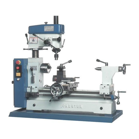
Page 5: Machine Terms
IDENTIFICATION Figure 4. The following is a list of controls and components on the Model B. Please take time to become familiar with each item and its location. These terms will be used throughout the manual and knowing them will aid in comprehension. Most of these terms will be shown in italics (italics) throughout the manual. MACHINE TERMS 1. Halfnuts lever 10. Micro feed handle 2. Power switch 11. Drilling milling clamp lever 3. Screw clutch lever ... -
Page 6: Assembly And Setup
ASSEMBLY & SETUP This section will cover the basics in assembly and setup. We recommend you complete assembly in the order in which it is presented to achieve the best results. HANDWHEEL The handwheel for the apron must be installed. Figure 5. Secure the handle with a screw driver. 1. Remove the acorn nut and washer from the cross feed Lead Screw. 2. Slide the handwheel onto the cross feed Lead Screw. Note the key way that is in the bore of the handwheel and orient it so it aligns with the key on the cross feed Lead Screw. 3. Secure the handwheel with the acorn nut and washer. 4. Secure the handle for the handwheel with a screw driver as in Figure 5. HAND CRANK The hand crank for the longitudinal manual feed must be installed. 1. The end of the Lead Screw has a small hole that is crossdrilled near its end. The hand crank has a similar ... -
Page 7: Lathe Chuck
Figure 6. Place roll pin in hole and tap with hammer Figure 7. Rotate chuck key to open/close jaws LATHE CHUCK The Model B Lathe / Mill comes equipped with a 3jaw (already installed). The 3jaw chuck is a scrolltype chuck, meaning that all three jaws move in unison when adjustments are made. Most 4jaw chucks, on the other hand, feature jaws which are adjusted independently. A 4jaw chuck can be used to hold square or rectangular stock. The 3 jaws, on a 3 Jaw Chuck, open and close using the chuck key provided. Please refer to Figure 7. Rotating the key clockwise closes the jaws. To use this mounting plate: 1. Fasten the plate to the 4jaw chuck using the screws provided with the chuck. 2. Fasten the plat to the spindle using the 3 screws that were removed from the 3jaw chuck. DO NOT mount chucks measuring larger than 5” in diameter on this spindle. Some 4jaw chucks may not readily mount to the back plate provided. It may be necessary to drill new mounting holes and/or resurface and shoulder the plate so the chuck may be mounted accurately and safely. ... -
Page 8: Lathe Chuck Removal
LATHE CHUCK REMOVAL To remove a chuck: 1. Place a piece of plywood across the lathe bed and position it just under the chuck. The board should be at least 8” wide and 10” long. 2. Locate the 3 socket head cap screws on the back of the back plate and remove 2 of them. Please see Figure 8. 3. Remove the last screw, whilst making sure to support the chuck with one hand. The chuck may come off as the last screw is removed, so it is important that you are ready to support its weight. 4. Remove the chuck. Chester UK Model B ... - Page 9 If the chuck is still tight on the spindle: Tap the edge of the chuck with a rubber or wooden mallet while supporting the bottom of the chuck with your free hand. If the chuck does not immediately come off, rotate the spindle approximately 60º and tap again. To install a chuck: 1. Place a piece of plywood across the lathe bed and position it just under the spindle. 2. Place a socket head screw into one of the holes in the back plate. Lift the chuck up to the spindle and align the threaded hole in the back of the chuck with the screw. 3. While supporting the weight of the chuck, turn the screw 3 turns. Do not tighten at this time. 4. Rotate the spindle and repeat step 3 on the last two screws. 5. Return to the first screw and tighten it a little more. Tighten the other screws as well but only enough that the gap between the chuck and the back plate remains even. 6. Finally, tighten all three screws until the gap between the chuck and the back plate is closed. Chester UK Model B ...
- Page 10 DEAD CENTRE The dead centre is used to support stock that is too long to be supported by the chuck alone. Stock protruding more than 2½ times its diameter, should be supported by a dead or rolling centre. Figure 9. Dead centre installed in tailstock. The tailstock barrel and centre have a Morse Taper #3. Before assembling these, insure that the mating surfaces are “white glove” clean. Clean the mating so they are free of dirt and oil. These parts will last longer and remain accurate when properly cleaned before assembly. Morse tapers will not interlock when dirt or oil are present on the mounting surfaces. Insert the end of the centre into the tailstock bore until it seats. The force of the centre contacting a mounted workpiece will fully seat the taper when the handwheel is tightened. ...
- Page 11 TOOL POST The Model B comes supplied with a 4 way turret tool post. It is designed to accept up to 14 tool bits. Other devices and holders may be installed into the tool post and arranged as in Figure 10. When more than one tool is secured into the tool post, changing from one tool to another is quickly done by loosening the lock lever (5) and rotating the post to the desired tool. A springloaded catch is installed below the tool post. This allows motion in only the counterclockwise direction. The catch causes the tool post to stop at the same rotational point for each tool placement. This feature can be used for some types of machining setups. Please note that the secureness of the tool post is not dependent upon the catch. Thus, ...
-
Page 12: Drill Chuck Removal
DRILL CHUCK The Model B comes supplied with a drill chuck and arbor that can be used in the tailstock on the lathe or in the spindle for the press. The arbor and drill chuck are assembled and installed into the spindle for the drill press spindle at the factory. DRILL CHUCK REMOVAL To remove the drill chuck from the drill press: 1. Unplug the machine. 2. Return the spindle to the highest position. 3. Remove the small plastic cap on top of the belt guard. 4. Grasp the drill chuck with one hand and unscrew the draw bar 3 turns with the other. 5. Secure the quill with the quill lock. 6. Tap on the end of the draw bar with a soft faced mallet as in Figure 12. Do not use a steel hammer! Damage to the draw bar, such as chipping, may occur. 7. Once the arbor has become loose, hold the drill chuck with one hand while unthreading the remainder of the draw bolt. Figure 12. Removing drill chuck Chester UK Model B ... -
Page 13: Drill Press Mounting
DRILL PRESS MOUNTING To mount the drill chuck into the drill press: 1. Remove the small plastic cap on top of the belt guard and slide the draw bar out of the spindle through the top. 2. Insert the arbor half way into the drill press spindle, then quickly slide it in place. 3. Replace the draw bar and thread it into the arbor. Do not over tighten! The draw bar only needs to be lightly tightened. Tightening any further will make it difficult to remove the arbor! LATHE MOUNTING Prior to mounting the drill chuck into the tailstock wipe the inside of the tailstock barrel and arbor down with a clean cloth and inspect them for nicks or scratches. Any irregularities on the surface of the arbor or inside the tailstock barrel will hinder the locking capability of the taper and should be dressed smooth with a fine file. To mount the drill chuck into the tailstock of the lathe, slide the arbor into the tailstock barrel about one half of the way. With a quick motion, finish sliding the chuck the rest of the way. This should seat it well into the tailstock barrel. Because the drill chuck arbor is threaded on the small end, removal requires the use of a mallet and a wooden dowel as in Figures 13. Tap along the back edge of the drill chuck on the left and then the right. ... - Page 14 MACHINE VICE The Model B comes supplied with a milling vice that also serves as the compound for the lathe. The 4 way tool post must be removed before using the vice. Loosen the lock handle and slide the tool post off of the compound / vice as Figure 14. The milling vice can be aligned to 1 of the 2 axis of the lathe or at any angle desired. Care must be given to setting the vice if a precision angle is needed. The following instructions are given to make the jaws parallel to the travel of the cross slide. 1. Remove the tool post as described above. 2. Loosen the swivel bolts on the compound / vice so it can swivel freely. Pivot the compound / vice so the jaws of the vice are roughly aligned with the cross slide. 3. Mount the drill chuck into the milling spindle and secure an indicator into it or, place a dial indicator mounted to a magnetic base on the bed as in Figure 15. 4. Position the cross slide and apron so the indicator point contacts the stationary vice jaw or a parallel mounted into the vice. 5. Move the cross slide with the hand wheel and watch the dial. Note the direction the needle is moving on the dial and by how much. 6. When the vice has moved so the indicator is at the other end of the parallel, pivot the vice one half the amount of motion detected in step 6. 7. Move the vice to the starting position and note the difference. Again, pivot the vice one half the difference. ...
-
Page 15: Lathe Speeds
LATHE CONTROLS LATHE SPEEDS Before using the lathe, the hub on the end of the lathe spindle must be pulled out as shown in Figure 16. To ease engagement of this hub, slowly rotate the spindle by hand while gently pulling the hub. Figure 16. Speed chart The speed of the lathe is controlled by the position of the belts on the pulleys. The chart in Figure 16 shows the various combinations of belt positions for achieving a range of 6 speeds. Example: rd To select a spindle speed of 310 R.P.M., place a belt on the 3 sheave (from the outermost sheave) of the nd middle pulley and the 2 sheave of the spindle pulley. Place a belt from the first sheave on the motor pulley to the first sheave of the middle pulley. ... -
Page 16: Feed Selection
FEED SELECTION Never move the feed rate lever while the machine is running. The Model B Lathe / Mill has 2 feed control levers which must be engaged in order to use the powerfeed or threading feature. The Feed Rate Lever, shown in Figure 19, controls internal gears that change the feed rate by a factor of 2. Turning the lever to position “l” will cause the Lead Screw to turn at twice the rate as when it is in position “ll”. When this lever is straight up, the gearing is in neutral and no power feed is available. Figure 19. Feed rate selection lever Important Do not force any lever on the machine. If the lever will not engage, rotate the chuck by hand while keeping light pressure on the selector. As the chuck rotates it aligns the gear teeth inside the selector box ... -
Page 17: Carriage Lock
HALF NUT The half nut lever is located under the left hand side apron as shown in Figure 21. This handle may be engaged and disengaged while the machine is still running and while making a cut. Move the lever to the down position and the half nut is engaged. Because the threads of the nut and Lead Screw will not always be aligned, engaging the half nut may require waiting until they are. Do not force the handle. Apply light pressure to the handle and when the threads are aligned the handle will engage. Figure 21. The half nut lever and carriage CARRIAGE LOCK The carriage lock lever is located under the right hand side of the apron as shown in Figure 21. This allows the carriage to be locked in place for precision facing operations while using the lathe or to make a set in a milling operation more rigid, among other things. CARRRIAGE CONTROLS The lathe has 3 handles for manual control of the tool bit during machining operations. One full turn on the cross slide or longitudinal hand cranks will produce 0.100” (one tenth of an inch) of motion. The cross slide and apron crank have dials with divisions showing relative motion. The compound has a direct reading scale on its side which is calibrated in 1 millimeter increments. The following is a description of ... -
Page 18: Tailstock Controls
Cross Slide – The hand wheel moves the compound slide across the lathe bed. Turning the dial clockwise moves the slide away from the operator. The motion of this slide is used for facing a workpiece and when advancing a cut for reducing a diameter. The dial has 100 divisions with each division representing 0.001” (one thousandths of an inch) of motion for the slide. The label above the dial reports that each line represents 0.002”. It is best to think of this as the amount of reduction in diameter on the part per line on the dial. Therefore, rotating the dial 10 marks will move the slide 0.010” and multiplying this amount by 0.002” equals 0.020”. Therefore, the diameter of the part will be reduced by 0.020” Apron – The longitudinal motion of the apron is controlled by the hand crank at the end of the lathe bed. See Figure 23. The motion of this slide is used when cutting along the length of a workpiece. This slide can also be operated with the power feed feature. Figure 23. Hand crank for the apron, Graduated Dials – Each dial can be rotated without turning the hand crank. This is helpful because the dial can be set to zero after the tool bit touches the part and the location of the slide and tool bit will be known. The graduated dial can be adjusted by holding the hand crank with one hand and turning the dial with the other. TAILSTOCK CONTROLS The tailstock comes supplied with a handwheel with graduated dial, barrel lock, tailstock lock and offset feature. Figure 24 shows the locations of each. Tailstock Handwheel – Turning the handwheel advances or retracts the barrel in the tailstock. The graduated dial on the handwheel is adjustable. ... -
Page 19: Drill Press Speeds
DRILL PRESS CONTROLS DRILL PRESS SPEEDS The speed of the drill press spindle is controlled by 2 groups of belts and pulleys. The belt positions on the end of the lathe control one speed range. See Figure 25. The belts and pulleys above the drill press control the other range. See Figure 26. Figure 25. Lower pulleys for speed changes Figure 26. Upper pulleys for speed changes Unplug the Lathe/Mill! Before using the drill press, the hub at the end of the lathe spindle must be adjusted to the “in” position. See Figure 27. To ease engagement of this hub, slowly rotate the drill spindle by hand while applying pressure to the hub. ... -
Page 20: Quill Lock Lever
To change belt position: 1. Unplug the machine. 2. Remove the Upper Belt Guard, loosen the cover securing the stud and pivot the belt tensioner to relax tension on the belt. See Figure 28. 3. While slowly turning a pulley, roll the belt up or down to the desired sheave. It is always easier to roll off of the larger pulley onto a smaller pulley. Do not allow fingers to become trapped between belt and pulley. 4. Pivot the belt tensioner until the belt is tight and secure the tensioner by tightening the stud. 5. Replace belt guard. Figure 28. Loosen stud to pivot belt tensioner. QUILL LOCK LEVER The height of the spindle can be locked with the Quill Lock Lever. Set the desired height with the Quill Lever and turn the lever down. The lever can be clearly seen on the bottom right hand corner of Figure 29. FINE FEED DOWN FEED The up and down motion of the drill press spindle is controlled just like any other drill press with a Quill Lever. But unlike most drill presses, the Model B is supplied with a Fine Down Feed Knob, indicated by the arrow in Figure 29. Figure 29. Move the handle while depressing knob. To activate this feature, rotate the Quill Lever while depressing the black knob in the middle of the centre of the hub as in Figure 29. The knob will engage and the spindle will no longer move using the Quill Lever. Rotating the Fine Down Feed knob in a clockwise direction will cause the spindle to go down. To ... - Page 21 ADJUSTMENTS GIBS There are three gib adjustments for the Model B. They are: the crossslide gib, the compound slide gib and the apron gib. Crossslide Gib – The gib on the crossslide is adjusted by tightening or loosening the 4 setscrews located on the right hand side of the slide. See Figure 30. The large setscrew in the middle is used to lock the cross slide in place during machining operations. Before adjusting the gib screws, loosen this setscrew. Figure 30. Tightening this screw tightens gib. The gib is held in place by the setscrews. Do not over tighten. The gib is properly adjusted when a slight ...
- Page 22 Apron Gib – There are 2 setcrews that tension the saddle gib. Before making adjustments to the saddle gib, ensure that the front lock lever is loose by turning it counterclockwise. See Figure 32. It is important the setcrews are tightened evenly. A slight drag should be detected while turning the hand crank at the end of the lathe. Figure 32. This bolt locks the apron in place. HEAD STOCK The Head Stock can be adjusted up or down to suit height requirements for different workpieces. Figure 33 shows the locking setscrew and lifting mechanism. To adjust the height, loosen the locking setscrew and rotate the lifting levers. When the Head Stock is at the desired height, lock in place with the lever. The Head Stock can be rotated around the column allowing it to be positioned out of the way during lathe operations. Figure 33. Elevating the Head Stock. Chester UK Model B ...
- Page 23 TAILSTOCK The tailstock on the Model B is aligned with the headstock at the factory. However, we recommend that you take the time to ensure that the tailstock is aligned to your desired tolerances. To align the tailstock: 1. Centre drill a 6” long piece of round cold rolled stock on both ends. Set it aside for use in step 4. 2. Make a dead centre by turning a shoulder to make a shank. Flip the piece over in the chuck and turn a 60° point. See Figure 34. As long as it remains in the chuck, the point of your centre will be accurate to your spindle axis. Keep in mind that the point will have to be refinished whenever it is removed and returned to the chuck. Figure 34. Finished dead centre. 3. Place a centre in your tailstock. 4. Attach a lathe dog to the bar stock and mount it between the centres. See Figure 35. 5. Turn approximately .010° off of the diameter. Figure 35. Bar stock mounted on centres. Chester UK Model B ...
- Page 24 Notice Before making adjustments to the tailstock, mount a dial indicator so that the dial plunger is on the tailstock barrel. See Figure 36. Figure 36. Adjusting for headstock end taper. 6. Measure the workpiece with a micrometer. If the stock is fat at the tailstock end, the tailstock needs to be moved toward you the amount of the taper. See Figure 36. If the stock is thinner at the tailstock end, the tailstock needs to be moved away from the operator by at least the amount of the taper. See Figure 37. Figure 37. Adjusting for tailstock end taper. 7. Loosen the 4 tailstock mounting bolts. Adjust the tailstock offset by the amount of the taper by turning the adjustment setscrews. See Figure 38. Turn another .010” off of the stock and check for taper. Repeat as necessary until the desired amount of accuracy is achieved. Figure 38. Tailstock offset adjustment screw. Notice DO NOT forget to lock down the tailstock after each adjustment. Chester UK Model B ...
-
Page 25: Control Panel
OPERATION CONTROL PANEL It is vital that you become familiar with the control panel before operating the Model B. Power to the motor is controlled through a series of switches mounted on the Lower Belt Guard. Figure 39 shows the various buttons and light. Please examine the layout and note the list of functions to the right before running the lathe / mill. Figure 39. Control panel components. 1. Power indicator light – shines when the power is turned on using the system reset switch. 2. Motor off button – turns motor off. 3. Motor on button – turns motor on. 4. Reversing switch – selects direction of rotation for spindles. Lift the cover to access the switch. Pushing ... - Page 26 TEST RUN Now that the lathe is securely in place and you’ve read the safety guidelines, it’s time to give the machine a test run. Before starting the machine: 1. Make sure the machine is properly grounded, the power switch is in the “OFF” position and the reversing switch is selected for forward. 2. Inspect the machine to ensure that all hand tools are out of the way, guards are in place and nothing is impeding the movement of the chuck. Check this by rotating the chuck by hand. 3. Rotate the System Reset Button and allow it to pop out. Push the start button on the control panel while keeping a finger poised over the stop button. The machine should run smoothly with little or no vibration or rubbing noises when it starts. Strange or unnatural noises should be investigated and corrected before operating the machine further. If the direction is reversed, contact our service department for further instructions. 4. I the lathe/mill is running correctly, push the stop button, wait for the machine to come to a complete stop and take some time to review the various controls. Chester UK Model B ...
-
Page 27: Reading The Charts
READING THE CHARTS Charts for the powerfeed and thread cutting features are located on the inside of the Lower Belt Guard. Figure 40 shows a segment of the chart and a brief description. Figure 40. Rates given in millimetres and inches. Please note that these charts reflect approximate apron movement per revolution. 1. Millimetres per revolution. 2. Gear layout for millimetres per revolution. 3. Inches per revolution. 4. Gear layout for inches per revolution. 5. Gear position A (all numbers in the row to the right represent number of teeth on gears used here). 6. Gear position B and C: combination gears listed as 125/127 or 120/60. 7. Gear position D (all numbers in the row to the right represent number of teeth on gears used here). 8. Feed rate selected for I. 9. Feed rate selected for II. 10. Approximate feed rates in inches or millimetres. FEED RATES Gearing for feed rates are detailed in Figure 40. In the example below we will be selecting gears for a feed rate of 0.002” per revolution. 1. Find 0.002” in the chart. 2. Locate the number in row A, which is above 0.002”. The number is 24, representing a gear with 24 teeth. 3. The number in row B above 0.002” is 120 and the number in row C is 60. These 2 numbers represent one of the 2 combination gears supplied with your lathe. 4. Finally, in row D you will find the number 120 that represents a gear with 120 teeth. 5. Looking at the gear layout we see that gear A (24 teeth) meshes with gear B (120 teeth) and that gear C (60 teeth) meshes with gear D (120 teeth). ... -
Page 28: Changing Gears
CHANGING GEARS Changing gears on the Model B is straight forward. Refer to the label found inside of the Lower Belt Guard for proper gear selection while following the example below. We will be changing the gears to those that would be used to set the machine for a 0.002” per revolution feed rate. These instructions assume that all of the gears need to be changed. The number of teeth are stamped on each gear. To begin: ... - Page 29 cap screw. Figure 43 shows the proper sequence. Slide the combination gear along the slot in the support arm until gear C meshes with gear D, as in Figure 44, and tighten the cap screw. Figure 43. Flats on bushing align slot. 8. Rotate the support arm until gears B and A are in mesh. Tighten the cap screw at the bottom of the gear support arm. Figure 45 shows the gears properly aligned and in mesh. Figure 44. Cutaway shows Gear C and D in mesh. Figure 45. Gears aligned and in mesh. Chester UK Model B ...
- Page 30 INCH THREAD The inch threading gear chart is illustrated in Figure 46. The layout is listed below to help identify the gears needed for cutting threads with inch pitches. The chart lists pitches in threads per inch. Figure 46. Rates given in millimetres and inches. 1. The column of numbers to the right of D represent the number of teeth on gears used in position D. 2. The numbers below A represent the number of teeth on gears used in position A. In this case 25 or 75 teeth. 3. Field of possible thread pitches. 4. The gear used in position B and C will always be the 125/127 combination gear. The 125 tooth gear will need to be oriented so it is in mesh with the gear in the A position. The Model B is capable of cutting many standard inch and metric threads. Follow the procedures listed in Changing Gears in the previous section and change the gears according to the chart for the thread desired. Figures 47 – 50 show the order the gears should be installed. This example shows gearing for cutting a 10 or 20 thread per inch (tpi) screw thread. (The Feed Rate Lever set to the I position will allow ...
- Page 31 Figure 48. 125/127 tooth combination gear. Figure 49. 30 tooth gear installed at “D”. Figure 50. 30 tooth gear installed at “D”. Chester UK Model B ...
-
Page 32: Metric Threading
METRIC THREADING The metric threading gear chart is illustrated in Figure 51. The layout is listed below to help identify gears for cutting threads with metric pitches. The chart below lists threads in millimetres or the theoretical amount of space one thread occupies. Figure 51. Rates given in millimetres and inches. Please note that charts reflect approximate apron movement per revolution. 1. The column of numbers below D represent the number of teeth on gears used in position D. 2. The numbers to the right of A represent the number of teeth on gears used in position A. 3. Field of possible thread pitches. 4. This gear will always have 120 teeth and will be intermediate to gears A and D. Example: To cut a thread with a pitch of 0.5mm we would select a 60 tooth gear and place it in the A position; we would select a 30 tooth gear and place it in the D position and we would use the 60/120 combination gear. However, you will need to place the gears in position A and D so that they both contact gear B only. You can accomplish this by turning gear D so the hub is on the outside as in Figure 52. Figure 52. Gear D is turned so hub is on outside. Chester UK Model B ... -
Page 33: Maintenance
MAINTENANCE LUBRICATION Your Model B will function best when it is clean and well lubricated. Take the time to wipe down and oil the machine before each use. We recommend using ISO 68 or SAE 20W nondetergent oil unless otherwise specified. Ball fittings will require the use of an oil gun. Depress the ball with the tip of the gun and squirt a little oil under pressure. Make sure to clean the machine after each use. Apron and cross slide – Apply lubrication directly to the dovetail ways of the apron and cross slide. Figure 53. Oil ports indicated by arrows. Compound – This slide is supplied with ball fittings on its top surface and should be oiled at the same time as the apron. See Figure 53. Figure 54. Oil external gears and bushing. Figure 55. Gearbox lubrication points External Gearing – Apply only a minimal amount of oil to the teeth of the end gears after assembly or each day. Avoid getting oil on the belt or pulleys when lubricating. Remove the gear indicated by arrow in Figure 54, and apply a few drops of oil to the bushing once a day. Bearings – Lubrication for the bearings occurs as the machine runs and oil circulates from the gear box. However, the bearings should be lubricated through the ball fittings indicated by the arrows in Figure 55. Apply oil every 3 hours of actual use and just before starting the machine each day. Chester UK Model B ... -
Page 34: Bearing Preload
Motor – The bearings used in the motor are shielded and lubricated for life, therefore, no lubrication is necessary. Lead Screw – Be sure to clean and lubricate the Lead Screw. There is also a bearing on the tail stock end that will require oil. Headstock Gearbox – The oil in the headstock should be changed after then first 2 hours of use, then every 6 months, depending on usage. We recommend that a light weight, nondetergent oil be used. Viscosity can range from 10W to 30W and may include multiviscosity oil in this same range. To remove the oil in the gear box, remove the change gear directly under the spindle, remove the cap screw indicated in Figure 57 and place a can under the drain hole to collect the waste oil. ... -
Page 41: Bed Assembly
BED ASSEMBLY Index no. Part no. Description Size Quantity 101 200SHQ40011001(1) Bed 1 102 200SGB/T911986 Split pin 5 x 25 103 200SHQ40011013 Lifting pin 4 104 200SHQ40011004 Tail stock base 1 105 200SHQ40011016 Gib 1 106 200SGB/T751985 Screw M8 x 15 2 107 200SGB/T771985 Screw M8 x 25 2 108 200SJB/T7271.31994 Knob M6 x 20 2 ... - Page 42 152 200SGB/T8791986 Spring pin 5 x 22 1 153 200SHQ400/301013 Adjusting washer 1 154 200SHQ400/301008 Gear bracket 1 155 200SGB/T97.11985 Washer 6 1 156 200SGB/T701985 Screw M6 x 30 1 157 200SHQ400/304002 Sleeve (left) 1 158 200SHQ400/304001 Shaft 1 159 200SGB/T10961979 Key 4 x 12 1 160 200SHQ400/3(SYMBOL)009 Change gear 1 161 ...
-
Page 43: Headstock Assembly
HEADSTOCK ASSEMBLY Index no. Part no. Description Size Quantity 201 200SGB11786 Pin 8 x 40 2 202 200SGB/T84885 Washer 10 6 203 200SGB/T93 Spring Washer 10 6 204 200SGB/T578086 Hexagon Head Screw M10 x 40 4 205 200STB/T7185 Screw M5 x 8 1 206 200SHQ400/302007N Headstock 1 207 200SGB/T11986 Pin B8 x 28 1 208 ... - Page 44 254 200SHQ40012003 Spindle Gland 1 255 200SHQ40012019 Oil Seal Of Spindle 1 256 200SGB/T29794 Roller Bearing 32007/p5 2 257 200SHQ400/302016 Gear A 1 258 200SGB/T7885 Screw M8 x 10 1 259 200SHQ40012013 Compensating Collar 1 260 200SHQ40012005 Bush 1 261 200SHQ40012004 Bevel Gear Wheel 1 262 200SGB/T30195 Bearing 51113 1 263 200SHQ40012009 ...
- Page 45 PROTECTOR ASSEMBLY Index no. Part no. Description Size Quantity 301 200SGB/T81885 Screw M5 x 6 2 302 200SHQ400/303001 Protector Cover 1 303 200SHQ400/303016 Protector Door 1 304 Pipe Fitting deg 8 2 305 200SGB/T6585 Screw M6 x 10 4 306 200SGB/T97.185 Washer 6 4 307 200SHQ400/303015(3) Protector 1 308 Junction Base 1 309 ...
- Page 46 TOOLPOST & SLIDE ASSEMBLY Index no. Part no. Description Size Quantity 401 200SJB/T2720.11994 Handle M8 x 65 1 402 200SGB/T9231988 Acorn nut M10 1 403 200SGB/T97011985 Washer 10 2 404 200SJB/T7273.31994 Handwheel B12 x125 1 405 200SHQ50010015 Scale ring base 1 406 200SHQ50010016 Spring piece 1 407 200SHQ40013010 Scale ring 1 408 200SGB/T701985 Screw ...
- Page 47 452 200SHQ40014T02012 Lead screw Tr12 1 453 200SHQ40014T02013 Lead screw bracket 1 454 200SJB/T720.101994 Handle BM8 x 25 1 455 200SGB/T1172000 Pin 3 x 16 1 456 200SHQ40014T02009 Bolt M10 x 100 1 457 200SHQ40014T02008 Tool post base 1 458 200SGB/T13581993 Spring 5 x 0.6 x 30 1 459 200SHQ40014007 Set pin 1 460 200SHQ40014003 Tool post 461 ...
-
Page 48: Tailstock Assembly
TAILSTOCK ASSEMBLY Index no. Part no. Description Size Quantity 501 200SJB/T7270.594 Handle M6 x 50 1 502 200SGB/T92388 Acorn nut M10 1 503 200SGB/T9785 Flat washer 10 1 504 200SJB/T7273.394 Hand wheel B12 x 100 1 505 200SHQ400/410015 Scale ring base 1 506 200SHQ50010016 Spring piece 1 507 200SHQ40013010 Scale ring 1 508 200SGB/T7085 Screw ... - Page 49 DRILLINGMILLING HEAD ASSEMBLY Index no. Part no. Description Size Quantity 601 200SGB/T7085 Screw M5 x 16 1 602 200SGB/T9387 Spring shim 5 1 603 200SGB/T89286 Washer B28 1 604 200SHQ40024001 Bevel gear (B) 1 605 200SHQ40024002 Compensating collar 1 606 200SGB/T109679 Key 6 x 14 1 607 200SGB/T681985 Screw 1 608 200SHQ40024003 Driving shaft ...
- Page 50 652 200SHQ40023008 Spring piece 1 653 200SHQ40023013 Collar 1 654 200SHQ40023001 Handle 2 655 200SJB/T7274.294 Knob 2 656 200SGB/T7185 Set screw M6 x 18 1 657 200SJB/T7271.594 Knob BM8 x 40 1 658 200SHQ40024011 Pulley shell (bottom) 1 659 200SGB/T961985 Washer 8 2 660 200SGB/T671985 Screw M8 x 14 2 661 ...
Need help?
Do you have a question about the B-Super 3-in-1 and is the answer not in the manual?
Questions and answers