
Related Manuals for Domestia DMC-008-001

Summary of Contents for Domestia DMC-008-001
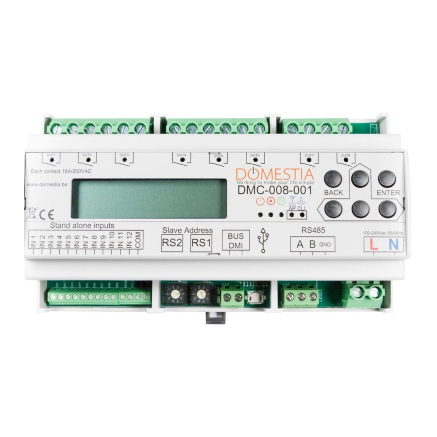
- Page 1 DMC-008-001/ DKS-008-001 USERS MANUAL DMC-008-001 DKS-008-001 Module 8 relay outputs www.domestia.be...
-
Page 3: Table Of Contents
Programming the push buttons (identification modules) ......12 Local input configuration ................12 Long press configuration (second function)..........12 Configuring the board with the «Domestia Home Manager©» application ... 13 Wi-Fi module configuration ................ 13 4.1.1 Wi-Fi AP mode configuration (WI-FI access point)........13 4.1.2 Wi-Fi client mode configuration (Wi-Fi access point connection) .... -
Page 4: Description
1. DESCRIPTION Module DMC-008-001 is a board with 8 relay outputs able to work alone, work as a master board (to manage up to 48 outputs) or work as a slave board. The DMC-008-001 module is also equipped with: • 12 digital outputs which are digitally configurable according to the installation’s needs or for autonomous use («stand alone»). -
Page 5: Connection
(8) RS485 for connecting to other boards: Blue LED - communication status between the boards (9) Module power 2. CONNECTION The DMC-008-001 module is designed to operate as a master board or as a slave board with the following as a master board: • A board with 12-output relays (DMC-012-002) •... -
Page 6: Chaining The Boards
Isolate the unused inputs Autorised star departure Cable type (0.25, 0.8...)* Foor previous module To following module(s) Or DMC-008-001 Isolate Max. Lenght : the unused It is advisable to place the identification inputs modules as close as possible to the pushbuttons. -
Page 7: Connecting The Digital Inputs ("Stand Alone" Mode)
2.4 CONNECTING THE DIGITAL INPUTS («STAND ALONE» MODE) DMC-008-001 AP CLI Slave Address RS485 100-240 Legend (1) 12 digital inputs This type of connection is for using the module alone, with no identification modules. E.g. For the contact renewal of an external clock, an alarm or any other device supplying dry... - Page 8 ORGANIZATION OF MENUS Types Outputs: Not configured Toggle 1 Domestia DMC-008 1.1 Switch outputs Toggle/Impuls ↨Output/Group xx <>ON/OFF Relay Timer ON/OFF Timer ON Timer/Shutter 2 Outputs 2.1 ↨Output XX Dimmer Stop ENTER + * 2.1.1Output XX Time: Type Configuration> <>Toggle ↨HH:mm:ss...
-
Page 9: Configuration Using The 6 Keys And The Lcd Screen
3. Configuration using the 6 keys and the LCD screen The DMC-008-001 is equipped with 6 keys for programming with visualisation via an LCD screen. Navigation in the menus is as follows: • The ENTER key to validate a selection or enter in a submenu. -
Page 10: Configuring The Times For Timers And Shutters
Function types available: • Not configured • Remote : pressing the push button reverses the state of the output. • Relay/Impulse : holding the push button down keeps the relay active while the button is pressed. • Timer ON/OFF : Pressing the push button reverses the state of the output. -
Page 11: Configuring Groups
3.3 CONFIGURING GROUPS The DMC-008-001 allows the creation of up to 22 groups. To create and configure the groups, you need to go to menu 3.1 and select the group you want to configure using the UP and DOWN keys. The second line displays the function type configured. Then... -
Page 12: Programming The Push Buttons (Identification Modules)
3. Press BACK to exit the programming of the push buttons. 3.5 LOCAL INPUT CONFIGURATION The DMC-008-001 module has 12 configurable digital inputs. They can be used with any dry contact. To configure the role of the local inputs, you need to go to menu 5.1. -
Page 13: Configuring The Board With The "Domestia Home Manager©" Application
The Wi-Fi module of the DMC-008-001 may operate as a Wi-Fi access point (we can connect directly to the DMC-008-001 without needing a Wi-Fi router or Internet connection) or as a Wi-Fi client (The DMC-008-001 is connected to your Wi-Fi router) or both simultaneously. -
Page 14: Starting The "Domestia Home Manager©" Application
4.3 STARTING THE «DOMESTIA HOME MANAGER©» APPLICATION Click on the «Home Manager©» icon to access these home screens. 4.4 INSTALLER LANGUAGE SELECTION Click on Language / Installer (bulb icon). Then click on the corresponding flag to determine the selected language. -
Page 15: Entering Your Installer Details
4.5 ENTERING YOUR INSTALLER DETAILS When your data is validated, you will return to the home screen by clicking on the icon (V). 4.6 CREATING A NEW CONFIGURATION Click on New (thermometer icon). Enter the installation’s details. * A magnifying class bearing «IP» allows you to automatically configure the IP address. Save the data by clicking «Valid». -
Page 16: Connecting To An Existing Configuration
If a connection with the board is not possible, you will be able to continue in «Not connected» mode. 4.7 CONNECTING TO AN EXISTING CONFIGURATION Click on Connection (solar panel icon). If the connection with the board is possible (tablet/computer/smartphone and DMC-008- 001 interconnected via a network and compatible IP parameters) then the application reads the content of the board. - Page 17 For the 12-output boards, the diagram represents the LEDs that must be lit when configuring the board address. For the 4- and 8-output boards, the diagram indicates the numbering to be applies to the wheels. Add the type and exact number of boards comprising your installation.
-
Page 18: Configuring The Slave Boards
Confirm the composition of your installation by pressing icon (V) on the left of the screen. Remember to configure the boards! (see below) 4.9 CONFIGURING THE SLAVE BOARDS 4.9.1 ADDRESSING THE 12-OUTPUT BOARDS (DMC-012-002, DMC-012-016, DMCV-006-002) : When you switch the board on, you have two seconds to press the key at the bottom to light up the BCE LEDs. -
Page 19: Addressing The 8-Output And 4-Output Boards (Dmc-008-001, Dmc-004-003, Dma-004-003, Dml-004-002, Dmd-004-002, Dmcv-002-003)
You can press the central key to validate and your board will be in «RUN» mode (LED: AE) DMCV-006-xx 4.9.2 ADDRESSING THE 8-OUTPUT AND 4-OUTPUT BOARDS (DMC-008-001, DMC- 004-003, DMA-004-003, DML-004-002, DMD-004-001, DMCV-002-003) : Simply turn the wheels to obtain the code indicated in the «Composition of the... -
Page 20: Output Configuration
As soon as you have validated the composition of the installation, a «Help» window appears. Then press on «stop/help». You can now start the configuration of the output names. 4.10 OUTPUT CONFIGURATION To configure an output, click on its name. A window opens allowing the name to be configured and the output type to be selected. -
Page 21: Group Configuration
«Shutters up». 4.11 GROUP CONFIGURATION Click on the icon The DMC-008-001 allows the creation of up to 22 groups. To create a group, click on the icon (+) and enter the name of the group by clicking on the name field. - Page 22 To configure groups, you need to select the type of group required : 1 «Toggle» or remote group type A group that switches on, switches off and varies the light intensity (dimmer) of the lighting outputs. A short press on the button reverses the state of the outputs. A long press enables the outputs and, in the case of a dimmer, varies the intensity.
- Page 23 7 «Simulation» group type Lighting output group for a presence simulation. When the push button activates the «Simulation», then the group’s outputs are lit up one after another in a random order and for a random duration (1 to 60 minutes). Then you select the outputs to be part of the group: Click on «Select outputs»...
-
Page 24: Saving The Configuration
4.12 SAVING THE CONFIGURATION Press the icon «REC» to save your configuration ! A progress indicator is displayed and the configuration is saved after a few moments. The application also creates a backup copy in a file. 4.13 PROGRAMMING THE PUSH BUTTONS 4.13.1 PROGRAMMING THE OUTPUTS To associate one or more buttons with an output, click on the output to be programmed. -
Page 25: Programming The Groups
To finish, press the push button(s) again. 4.13.2 PROGRAMMING THE GROUPS To associate one or more push buttons with a group, click on the icon Then click on the group to be programmed then on the orange key «Click here to program the PB». -
Page 26: Warranties
• Damage due to electrical installation faults • Repair attempts made by the customer or a third party are not permitted • Damage caused by accident, force majeure or other causes for which Domestia cannot be held responsible • Fault not effecting the proper functioning or proper use of the equipment. - Page 28 Jean Jaurès, 176 4430 Ans Belgium +32 4 372 07 16 +32 4 372 07 19 info@domestia.be...
Need help?
Do you have a question about the DMC-008-001 and is the answer not in the manual?
Questions and answers