Advertisement
Quick Links
Specifi cations
Current Ranges
Field Selectable from 0-2000A
Current Measurement
range 0-2000A@600V, CAT III
Output Signal
4-20mA, Loop Powered
Output Limit
23 mA
Power Supply
24VDC nominal, 40VDC max.
Overvoltage Cat. I, Class 2 or power limited
power supply
Accuracy
1.0% FS
Measurement
True RMS or Average Responding
Frequency Range
ATR: 10-400 Hz
AT:
50-60 Hz, Sinusoidal
Isolation Voltage
3kV
Response Time
500 ms (to 90% of step change)
Environmental
-4 to 122°F (-20 to 50°C) operating ambient
temperature.
0-95%RH, non-condensing
Pollution Degree 2
Altitude to 2000 meters
Case
UL 94V-0 Flammability rated thermoplastic
Listing
UL and cUL Listed
CE Certifi ed
RoHS Compliant
Power Supply
Minimum Power Supply = 12 VDC + Total Loop Voltage Drop
32V
LOOP
22V
POWER
(VDC)
12V
0
250
500
Total Loop Impedance (Ohms)
Caution! Risk of electric shock or per-
sonal injury
Safe operation can only be guaranteed if the
transducer is used for the purpose for which
it was designed and within the limits of the
technical specifi cations. When this symbol
is used, it means you should consult all
documentation to understand the nature of
potential hazards and the action required to
avoid them.
Caution! Risk of hazardous voltage
When operating the transducer, certain parts
may carry hazardous live voltage (e. g. pri-
mary conductor, secondary terminals). The
transducer should not be put into service if
the installation is not complete.
Model Number Key
AT R
3 - 420 - 24L - FL
RANGE
2 -
3 - 375, 500, 750 A
4 - 1000, 1333, 2000 A
Measurement
R -
(Blank) - Average Responding
SENSOR TYPE:
AT - AC current sensor, 4-20 mA output
loop powered
Operating
Range
Know Your Power
750
1000
Other NK Technologies Products Include:
AC & DC Current Transducers
AC & DC Current Operated Switches
1φ & 3φPower Transducers
Current & Potential Transformers (CTs&PTs)
3511 Charter Park Drive, San Jose, CA 95136
Phone: 800-959-4014 or 408-871-7510
Fax: 408-871-7515
sales@nktechnologies.com, www.nktechnologies.com
CASE STYLE
FL- Fixed core
POWER SUPPLY:
24L- 24VDC Loop Powered
OUTPUT:
420 - 4-20mA
100, 133, 200 A
True RMS
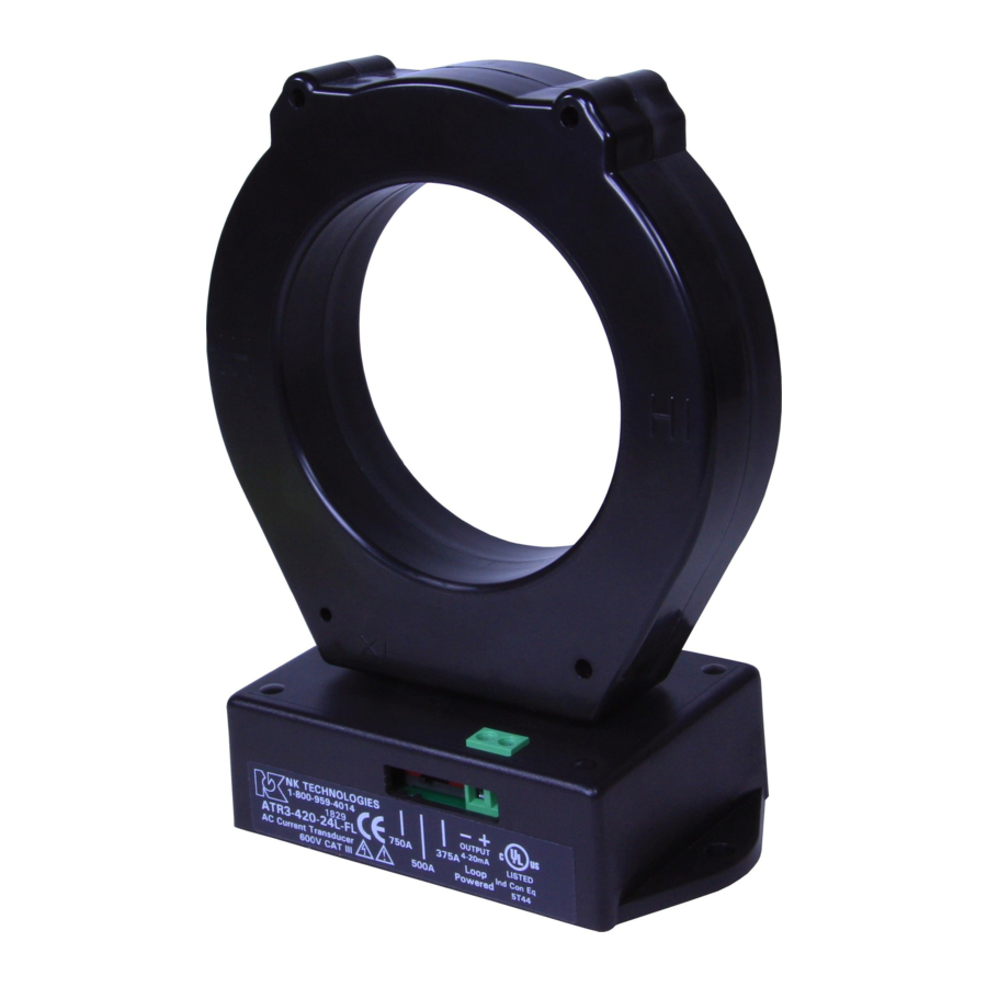
INSTRUCTIONS
AT & ATR 2, 3 & 4 SERIES
AC Current Transducers
4-20mA Output
True RMS or Average Responding
Quick "How To" Guide
1. Run the wire you are monitoring through aper-
ture.
2. Mount the sensor to a surface if needed.
3. Connect output wiring.
A. Use up to 14 AWG 75/90˚ C copper wires.
B. Make sure output load does not exceed product
specifi cations.
C. Connect 24 VDC power supply and load in
series.
4. Select Range
A. Chose correct range by positioning the Range
switch.
AT/ATR 2/3/4 Series 292001301-3
Advertisement

Related Manuals for NK TECHNOLOGIES AT 2 Series


Summary of Contents for NK TECHNOLOGIES AT 2 Series
- Page 1 3. Connect output wiring. Safe operation can only be guaranteed if the Other NK Technologies Products Include: transducer is used for the purpose for which A. Use up to 14 AWG 75/90˚ C copper wires. it was designed and within the limits of the AC &...
- Page 2 Description Output Wiring AT and ATR Series transducers combine a current trans- Connect control or monitoring wires to the sensor. Use former and a signal conditioner into a single package. up to 14 AWG 75/90˚ C copper wire and tighten terminals This provides higher accuracy, lower wiring costs, easier to 4.4 inch-pounds torque.