Advertisement
Specifi cations
Power Supply
24 VAC/DC( +/- 10%) Note: Not isolated
from output signal.
NOTE:
Power Supply and output signal ARE NOT isolated. Do
not connect the negative terminals to a common point when
using the 24 V powered models.
120 VAC (+/-10%) Note: Power supply
is isolated from output signal.
Power Consumption
<6.0 VA
Outputs
Four outputs, three proportional to the
current in that phase, one an average of
all three.
Signal Type
Output Signal
4-20 mA
0-5 VDC
Impedance Limits
0-10 VDC
Accuracy
1% FS
Response Time
220 ms (to 90% of step change)
Frequency Range
AT: 50-60 Hz
ATR: 30-100 Hz
Over Current Limit
6X range setting for one second
Output Terminals
Finger-safe captive screw, 14-22 AWG
Torque to 5-7 inch-pounds
Isolation Voltage
To 1250VAC
Enclosure
ABS, UL94 V0 Flammability rated
Environmental
-4 to 122°F, -20 to 50°C
Approvals
UL/cUL listed E342812
Model Number Key
ATR 3 - 420 - 24U - TH
Output Signal
Impedance
420
<500 Ω
005
010
>2K Ω
>2K Ω
Current Ranges
1 0-10, 0-15 and 0-30A
2 0-30, 0-50, and 0-100A
3 0-100, 0-150 and 0-200A
AT: Average Responding
ATR: True RMS
Other Available Products Include:
DC Current Switches, Ground Fault Sensors
AC & DC Current Switches
Power Transducers
Current & Potential Transformers (CTs&PTs)
3511 Charter Park Drive, San Jose, CA 95136
Toll free: 800-959-4014, Phone: 408-871-7510
Fax: 408-871-7515
sales@nktechnologies.com, www.nktechnologies.com
Housing Type
TH Three Hole
Power Supply
24U 24 VAC/DC (non-isolated)
120 120VAC (isolated)
4-20mA
0-5 VDC
0-10 VDC
INSTRUCTIONS
AT/ATR-TH Series
AC Current Transducer
w/Proportional Analog Outputs
Quick "How To" Guide
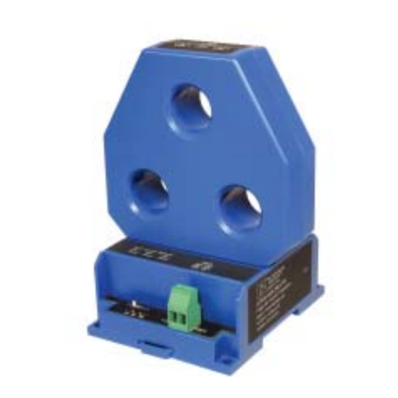
1. Mount AT/ATR-TH Current Transducer to DIN rail or
panel in suitable enclosure.
2. With monitored load off, install each phase through the
sensing windows. Designate one phase as A, B and C.
3. Select the current range using the slide switch.
4. Connect output terminals + and - using 22-14 AWG
copper wires rated 70/90°C. Tighten to 5-7 inch-pounds
torque.
5. Connect power supply voltage to terminals 9-10
6.
The output will be proportional to the current in each
phase, plus one which is the average of the three.
7. Any of four analog signals can be used independently, or
all four can be used at the same time.
APT-TH Instruction Sheet Rev 2 04/18 p/n 292000609
Advertisement
Table of Contents

Related Manuals for NK TECHNOLOGIES AT-TH Series


Summary of Contents for NK TECHNOLOGIES AT-TH Series
- Page 1 Specifi cations Model Number Key Power Supply 24 VAC/DC( +/- 10%) Note: Not isolated ATR 3 - 420 - 24U - TH from output signal. NOTE: Power Supply and output signal ARE NOT isolated. Do not connect the negative terminals to a common point when Housing Type INSTRUCTIONS TH Three Hole...
- Page 2 Description Wiring Schematic Diagram Troubleshooting AT/ATR-TH Series current transducers are intended to Sensor has no output: PLC, 0-10 VDC monitor consumption of three phase loads. They provide A. Power source is not energized or connected to the Controller, etc. 0-5 VDC an analog signal proportional to the current in each of the 4-20 mA transducer.
Need help?
Do you have a question about the AT-TH Series and is the answer not in the manual?
Questions and answers