Table of Contents
Advertisement
Quick Links
Advertisement
Table of Contents

Related Manuals for Nodka eBOX-3000

Summary of Contents for Nodka eBOX-3000
- Page 1 User Manual Ver1.0 eBOX-3000 Embedded Fanless BOX PC...
- Page 2 Copyright Copyright notice The information in this document is subject to change without prior notice in order to improve reliability, design and function and doesn’t represent a commitment on the part of manufacturer. In no event will the manufacturer be liable for direct, indirect, special, incidental, or consequential damage arising out of the use or inability to use the product or documentation, even if advised of possibility of such damages.
- Page 3 Manual conventions WARNING: Warnings appear where overlooked details may cause damage to the equipment or result in personal injury. Warnings should be taken seriously. CAUTION: Cautionary messages should be heeled to help reduce the chance of losing data or damaging the product. NOTE: These messages inform the reader of essential but non-critical information.
- Page 4 Declaration of Conformity This restriction is subject to provide protection for system operation in business environment, which will produce, use and transmit radio frequency energy. Without notice of the instructions of the correct installation and use, it may cause harmful interference to radio communication.
- Page 5 Technical Support and Service Please visit the Nodka website http://en.nodka.com to get more details. If you need additional assistance, please contact your system reseller or vendor. Please have the following information ready before you call: Product name and serial number...
- Page 6 Ordering Information Description Product code EBOX-3000 No CPU/No memory/No hard disk/6*RS232(2*RS232/485Optional)/ 2 Gigabit Ethernet ports/8*USB2.0ÿ 4 of them support USB3.0ÿ /DVI/VGA//HDMI/PS2/Audio card/DC12~24V input /Two-year warranty EBOX-3000-E No CPU/No memory/No hard disk/6*RS232(2*RS232/485Optional)/ 2 Gigabit Ethernet ports/8*USB2.0ÿ 4 of them support USB3.0ÿ /DVI/VGA//HDMI/PS2/ Audio card /extend...
-
Page 7: Table Of Contents
Content Chapter 1 Overview........................ 1 Introductions........................2 1.2 Key Features........................2 1.3 External Overview......................3 Specifications........................3 Dimensions........................5 1.6 Assembly and disassembly..................... 5 1.7 COM Jumper setting....................... 6 Chapter 2 System installation....................8 2.1 Connectors Definition...................... 9 2.2 BIOS Setup........................ -
Page 8: Chapter 1 Overview
Chapter 1 Overview... -
Page 9: Introductions
Introductions eBOX-3000 is a fanless mini eBOX-3000 is a fanles mini PC based on Intel® Core™ i3/i5/i7/Celeron high performance processor, impact and with large aluminum fin radiator, with no cable inside. The performance has increased 30% than the 6th/7th generation Intel® Core™ processor. It uses dual channel DDR4 SODIMM, up to 32GB. -
Page 10: Specifications
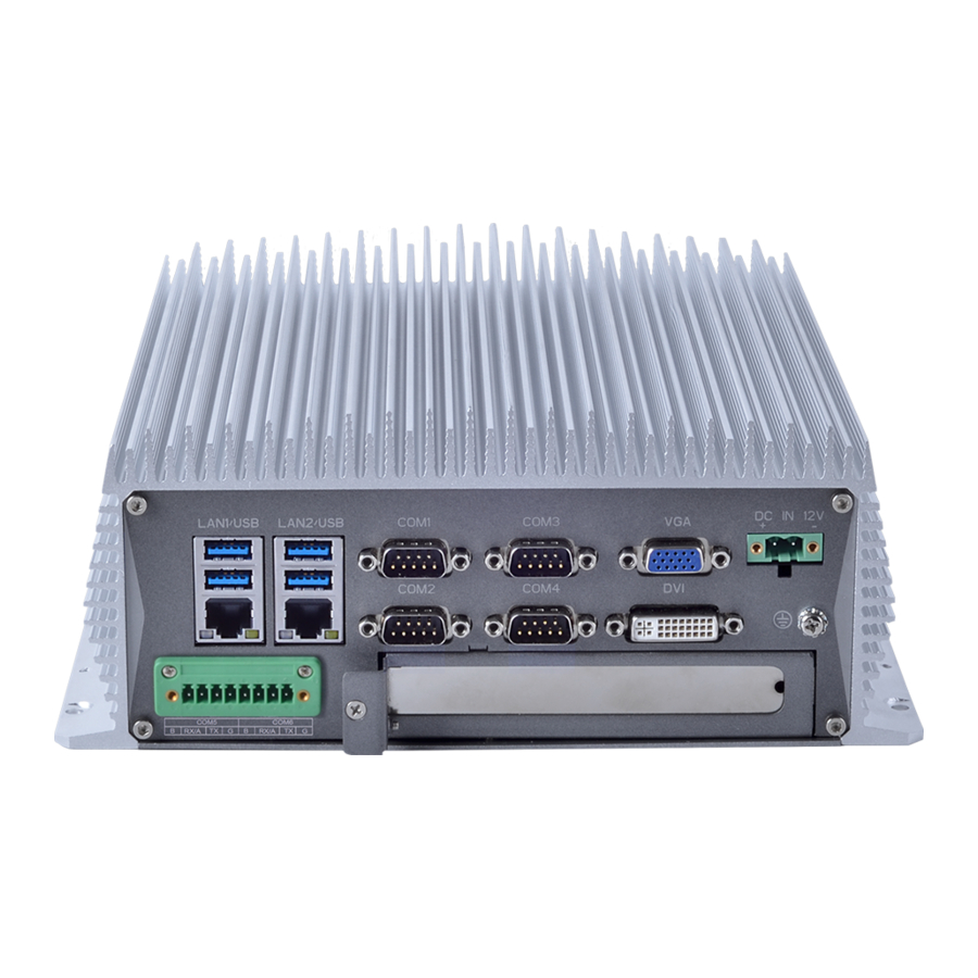
Figure 1-1 Front and rear overview of eBOX-3000 Specifications SYSTEM Ebox-3000 Processor Intel® Core™ 6th / 7th generation i7 / i5 / i3 / Pentium / Celeron Chipset Intel H110 Express Chipset BIOS AMI EFI 64Mbit Memory Architecture DDR4-2400MHz Capacity... -
Page 11: Dimensions
Type Power Input voltage 12-24VDC ±10% Minimum Input 12V/10A, 120W Power Adapter Optional No-load Power 27Watt Dissipation Full-load 55Wattÿ According to the CPU set, total power not exceeding 100Wÿ Mechanism Box structure Aluminum alloy BOX Parameters Mounting Support Desktop and Wall-mounted mounting Dimensions 240mm x 240mm x 95mm (9.45"... -
Page 12: Assembly And Disassembly
Assembly and disassembly eBOX-3000 has a unique structure design which makes COM port settings easily and quickly as well as the replacement of the hard disk. 1.5.1 Hard disk replacement Step1. Find the orange HDD cover. Step 2. Pull out the blue sign. -
Page 13: Com Jumper Setting
Step 3. Paste the pull & push sticker and the height adjusting frame on HDD. Step 4. Insert the hard disk into the slot along the chute. Cover the orange hard disk cover. COM Jumper setting Step 1. Turn the device to the backside, then screws the screws as shown in the figure below. - Page 14 Step 2. Remove the cover. Then use jumper cap to set jumper. The definition of J232_485_6 jumper configuration is in the table below. Definition Definition NDCD6 SIN6_485TX- RS485_TX-6 PWMOUT SOUT6_485TX+ RS485_TX+6 COM_RST RST_OF6...
-
Page 15: Chapter 2 System Installation
Chapter 2 System installation... -
Page 16: Connectors Definition
Connectors Definition Figure 2-1 Definition of connectors 2.1.1 COM Ports eBOX-3000 has 6 COMs. COM 1~4 are R232 type DB9 connector. PIN9 on DB9 defaults RI. The definitions are as follows: SIGNAL RS232 COM 5~6 is 8P. Definitions are as follows. - Page 17 COM5 RS232 RS485 485- 485+ 485- 485+ Default RS232 RS485 2.1.2 We provide a standard single deck USB port in front panel and 2 x 2 standard double- deck USB interface on I/O interfaces, you can use the 5 USB interfaces at the same time.
- Page 18 SIGNAL Date- Date+ SIGNAL Date- Date+...
- Page 19 2.1.3 Audio interface (LINE_OUT) We provide a standard Ø3. 5 Phone Jack audio output interface (LINE_OUT), you can use it directly. 2.1.4 Ethernet Interfaces (LAN1, LAN2) We provide two 10/100/1000Mbps RJ-45 Ethernet interfaces, you can use it directly. There are two status indicators, links status on the left side, data transmission status on the right side.
- Page 20 KB_Data MS_DATA KB_Clock MS_Clock 2.1.6 VGA connector We provide a standard DB15 monitor interface, you can connect it directly. SIGNAL SIGNAL GREEN BLUE DDC_Data 5 10 15 GND_R GND_G DDC_Clock GND_B 2.1.7 DVI interface We provide a DVI-D interface in the rear panel which makes double display with VGA possible.
- Page 21 2.1.10 PWR, hard drive status indicators We provide a set of indicators to show the status of the power and the hard drive. Continuous green light indicates that the power is switched on. Flashing red light on hard drive indicator means that the hard drive is reading/writing data.
-
Page 22: Bios Setup
BIOS Setup The BIOS is programmed onto the BIOS chip, the BIOS setup program allows changes to certain system settings. This chapter outlines the options that can be changed. NOTE: Some of the BIOS options may very throughout the life cycle of the product and are subject to change without prior notice. - Page 23 Save all the CMOS changes and reset The menu bar which is anchored to the top of the BIOS screen has the following main items: ðØ Main – Changes the basic system configuration. ðØ Advanced – Changes the advanced system settings ðØ...
- Page 24 System Date: Set the system date, the date format is MM/DD/YY Day: Note that the ‘Day’ automatically changes when you set the date. 2.2.4 Advanced setting The Advanced BIOS Setup screen is shown as below. The sub menus are described on the following pages.
- Page 25 Advance - ACPI Configuration...
- Page 26 SATA Configuration Display Configuration...
- Page 27 AC Power Loss Wake up Settings...
- Page 28 Super IO Configuration USB Configuration...
- Page 29 2.2.5 Chipset configuration...
- Page 30 2.2.6 BOOT Configuration 2.2.7 Security settings...
- Page 31 2.2.8 Save & Exit Option Save Changes and Exit When you have completed system configuration, select this option to save your changes, exit BIOS setup and reboot the computer. So the new system configuration parameters can take effect. 1. Select Exit Saving Changes from the Exit menu and press Enter. The following message appears: Save Configuration Changes and Exit Now? [Ok] [Cancel] 2.
-
Page 32: Driver Installation
Driver installation NOTE: Please Install Operating system first. All drivers of eBOX-3000 are under the Windows XP. When first using the system, users need to set up corresponding drivers to make sure all functions are normal. To install the drivers, please follow the steps below: Step 1. - Page 33 To install the chipset diver, please follow the steps below. Step 1. Right select management into the computer management window. Then right click to update SM bus controller as shown in the figure below. Step 2. Double-click Chipset. Step 3. Click SetupChipset.
- Page 34 Step 4. Click Next. Step 5. Read the license agreement. Click Accept.
- Page 35 Step 6. Click Restart Now. 2.3.2 Graphics driver To install graphics diver, please follow the steps below. Steps 1. Select the application of graphics driver.
- Page 36 Step 2. Click Automatically run WinSAT and enable the Windows Aero desktop theme (if supported). Click Next. Step 3. Read license agreement. Click Yes.
- Page 37 Step 4. Click NEXT to continue. Step 5. Click Next.
- Page 38 Step 6. Select Yes, I want to restart this computer now.. Click Finish to complete the installation. 2.3.3 Audio driver To install audio diver, please follow the steps below. Step1. Double click the folder of audio driver.
- Page 39 Step 2. Click Setup Step 3. Click Next to continue...
- Page 40 Step 4. Click Finish 2.3.4 LAN driver To install LAN driver, please follow the steps below. Step 1. Right select management into the computer management window. Then right click to update Intel(R) I210 Gigabit Network Connection#2 as shown in the figure below.
- Page 41 Step 2. Choose Browse my computer for diver software. Step 3. Wait for the installation process to complete.
- Page 42 2.3.5 Me diver To install ME driver, please follow the steps below. Step 1. Click SetupME Step 2. Click Next Step 3. Click Next.
- Page 43 Step 4. Read license agreement. Choose I accept the terms in the License Agreement., Click Next.
- Page 44 Step 5. Click Finish.
-
Page 45: Appendix A Safety Precautions
Appendix A Safety Precautions CAURION: The precautions outlined in this chapter should be strictly followed. Failure to do so may cause permanent damage to the product. General Safety Precautions Please read the following safety precautions carefully. Make sure you always follow the precautions. -
Page 46: Anti-Static Precautions
Anti-static Precautions WARNING: During the installation of the product, failure to take ESD precautions may result in permanent damage to the device and cause severe injury to the user. Electrostatic discharge (ESD) may cause severe damage to electronic components of product, especially during dry weather. Therefore, please strictly observe the anti- static precautions when opens the product to handle any electrical components inside. -
Page 47: Maintenance And Cleaning Precautions
CAURION: If the battery is replaced with the wrong type, there might be a risk of a battery explosion. Only certified engineers can replace the on-board battery. NOTE: Disposal of used batteries must be in accordance with local environmental regulations. Within the European Union: EU-wide legislation, as implemented in each Member State, requires that waste electrical and electronic products carrying the... - Page 48 A.4.1. Maintenance and Cleaning Prior to cleaning any part or component of the product, please read the details below. Except for the LCD panel, never spray or squirt liquids directly onto any other components. To clean the LCD panel, gently wipe it with a piece of soft dry cloth or a slightly moistened cloth.
-
Page 49: Hazardous Materials Disclosure Table For Ipb Products Certified As Rohs Compliant Under 2002/95/Ec Without Mercury
Appendix B Hazardous Materials Disclosure Table for IPB Products Certified as RoHS Compliant Under 2002/95/EC without Mercury The details provided in Appendix B are to ensure that the product is compliant with the Peoples Republic of China (China) RoHS standards. The table below acknowledges the presences of small quantities of certain materials in the product, and is applicable to China RoHS only. - Page 50 B-1 Poisonous or hazardous substances or element in products Component Toxic or Hazardous Substances and Elements Hexavalent Chromium Polybrominated Biphenyls Polybrominated Diphenyl Ethers Lead (Pb) Mercury (Hg) Cadmium(Cd) (Cr(VI)) (PBB) (PBDE) Housing Printed Circuit Board Metal Fasteners Cable Assembly Fan Assembly Battery O: The quantity of poisonous or hazardous substances or elements found in each of the component's parts is below the SJ/T 11363-2006-stipulated requirement.
Need help?
Do you have a question about the eBOX-3000 and is the answer not in the manual?
Questions and answers