PACSystems RX3i User Manual
Power sync and measurement system
Hide thumbs
Also See for RX3i:
- Important product information (19 pages) ,
- User manual (14 pages) ,
- Manual (6 pages)

Related Manuals for PACSystems RX3i


Summary of Contents for PACSystems RX3i
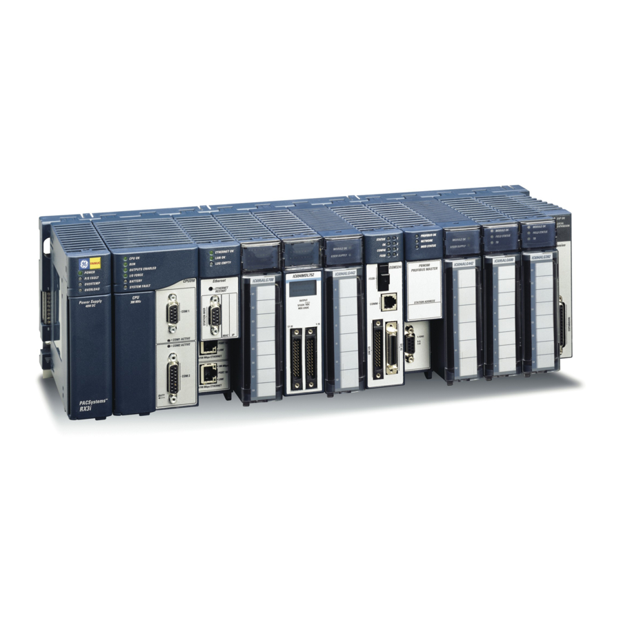
- Page 1 User Manual GFK-2749A Jan 2020 PACSystems RX3i POWER SYNC AND MEASUREMENT SYSTEM USER MANUAL...
-
Page 2: Table Of Contents
User Manual Contents GFK-2749A Jan 2020 Contents Chapter 1: PSM Module Description and Specifications ... 1 PSM System Features ................... 1 PSM Module ......................2 Terminal Assembly ....................3 Connectors ......................3 User-Supplied Equipment ..................4 PSM Part Numbers ....................4 Specifications ...................... - Page 3 User Manual Contents GFK-2749A Jan 2020 3.1.3 ANSI Protection Parameters ..............37 3.1.4 Power Consumption ................41 3.1.5 Terminals ....................41 Data Transfer ..................... 41 3.2.1 PSM Status Flags ..................41 3.2.2 Mode Control Bits Sent to PSM module ........... 50 3.2.3 Parameters sent to PSM Module ..............
- Page 4 GFK-2749A Jan 2020 Warnings, Caution Notes as Used in this Publication Warning notices are used in this publication to emphasize that hazardous voltages, currents, temperatures, or other conditions that could cause personal injury to exist in this equipment or may be associated with its use. In situations where inattention could cause either personal injury or damage to equipment, a Warning notice is used.
-
Page 5: Chapter 1: Psm Module Description And Specifications
Demand penalty cost reduction/load shedding The PSM system consists of: • PSM module – A standard IC694 module that mounts in an RX3i main rack. The PSM module provides the DSP capability. • Terminal Assembly – A panel-mounted unit that provides the interface between the PSM module and the input transformers. -
Page 6: Psm Module
In addition to configuring the PSM module upon project download from PME, the RX3i CPU can control the PSM module by updating configuration data from the RX3i in the form of %AQ data words and %Q mode control bits during each sweep. -
Page 7: Terminal Assembly
GFK-2749A Jan 2020 Green The module is operating correctly and communicating with the RX3i. The module is operating without backplane communication. The module is not operating. Green, During the period when GREEN is ON, Grid 2 can be connected to blinking Grid 1. -
Page 8: User-Supplied Equipment
User Manual Chapter 1 GFK-2749A Jan 2020 A four-pin pluggable connector provides two isolated solid-state relay contacts that close when the correct voltage, phase, and relative frequency differences match the configured criteria for synchronization of the GRID1 and GRID2 signals Note: The Terminal Assembly is not equipped with CT shorting-bars. -
Page 9: Specifications
Total Power Dissipation 2.0 W max. Isolation from Backplane 1500 VDC Host Controller Compatibility RX3i CPUs For specific versions supported, refer to “Functional Compatibility” in the Important Product Information document, GFK-2748. Maximum number of PSM modules per No restrictions, as long as the power supply has sufficient... - Page 10 2 words Data Exchange Time Between RX3i CPU and PSM A complete data exchange between the PSM and RX3i occurs during each controller scan. Minimum scan time is 3.5ms per PSM module in the backplane. Minimum data update rate is one power line period.
-
Page 11: System Operation
User Manual Chapter 1 GFK-2749A Jan 2020 Power Measurement Configurations Four-wire three phase wye systems: 3 PTs and 3 CTs plus Neutral CT (optional) Three-wire three phase delta systems: 2 PTs and 2 CTs Three independent single phase systems: 1 PT and 1 CT for each phase Three-wire single phase systems: 120/240 (2 PTs and 2 CTs) Operating Environment Enclosure mounting... -
Page 12: Autonomous Operation
1.8.1 Autonomous Operation The PSM is a semi-autonomous module running on the RX3i backplane. If the PLC goes to Stop Mode, or the CPU is lost due to over temperature or a watchdog timeout, the PSM continues to operate with the last directive received from the CPU. If the CPU had requested the synchronization of Grid 1 and Grid 2, when all sync parameters are met, the PSM will assert RelayCloseOK and close its relay output contacts, even when the PLC is in Stop Mode. -
Page 13: Ansi Functions Supported
User Manual Chapter 1 GFK-2749A Jan 2020 Frequency Measurement Notes PSM preferentially chooses Grid 1 VA zero crossing as the reference for signal sampling. In the absence of Grid 1 VA, PSM uses Grid 2 VA zero crossing. In the absence of either VA signal, grid frequencies will be reported as 0Hz, and the remaining inputs will be sampled at a rate of 128 samples per 25ms. - Page 14 User Manual Chapter 1 GFK-2749A Jan 2020 to lead the signal on the VC terminal by 120 degrees. Unused “reconstructed” signal inputs are ignored for Phase Sequence detection. The current signals are not monitored for Phase Sequence. ANSI 50 – Instantaneous Over-current Protection This function provides three-phase protection against overloads and phase-to-phase short- circuits.
- Page 15 User Manual Chapter 1 GFK-2749A Jan 2020 ANSI Functions for GRID 2 (Generator/Generator Grid) Protection WARNING It is the responsibility of the user to verify that the system has sufficient frequency stability to maintain the current phase trend during the synchronization process. This requirement is especially true for long breaker delays.
- Page 16 User Manual Chapter 1 GFK-2749A Jan 2020 Phase Angle For synchronization, the two grids must be connected when the phase angle difference between the grids is in the range of ±PHASE_SHIFT_THR, and ideally at the point when the two grids are exactly in phase. The phase shift threshold represents an angle window in electrical degrees (usually ±10°) around the 0°...
- Page 17 User Manual Chapter 1 GFK-2749A Jan 2020 PhaseShiftOK = On @ Angle Delay PhaseShiftOK = Off @ –(Angle Delay+2º) Figure 5 Slow Rotation: Angle Delay ≤ (Phase_Shift_Thr - 2º)/2 If the request to sync is on or received by the PSM module at any time in the green region (while PhaseShiftOK = on), the CloseRelayOK status bit will be set and the IC694ACC200 output contacts will close.
- Page 18 User Manual Chapter 1 GFK-2749A Jan 2020 Fast Rotating Phase Angles For faster rotating phase angles where Angle Delay > (Phase_Shift_Thr - 2º)/2, these equations apply: PhaseShiftOK = On @ Angle Delay PhaseShiftOK = Off @ Angle Delay – Phase_Shift_Thr Figure 6 Fast Rotation: Angle Delay >...
- Page 19 User Manual Chapter 1 GFK-2749A Jan 2020 PhaseShiftOK = Off @ 15.9º {Angle Delay – Phase_Shift_Thr} If Sync is requested while PhaseShiftOK = On, then CloseRelayOK will be set to On for the Angle Delay + 24 cycles. At ΔF = 0.09Hz and 60Hz, the PhaseShiftOK window is 800ms (25.9⁰) + 400ms = 1.2 seconds.
- Page 20 User Manual Chapter 1 GFK-2749A Jan 2020 mover power rises above the REV_PWR_THR for a time period longer than REV_PWR_ DELAY. The REV_PWR_THR is a percentage of the nominal power which, in a 3-phase system, is three times the nominal voltage multiplied by the nominal current. ANSI 47 –...
- Page 21 User Manual Chapter 1 GFK-2749A Jan 2020 ANSI 81O – Over-frequency Protection Detection of abnormally high frequency compared to the nominal frequency, to monitor power supply quality. The alarm will be triggered if a circuit’s frequency is above the nominal frequency plus OVER_FRQ_THR for a time period longer than OVER_FRQ_DELAY.
-
Page 22: Chapter 2: Installation
User Manual Chapter 2 GFK-2749A Jan 2020 Chapter 2: Installation General Warnings/Cautions WARNING Installation and wiring procedures must be performed by qualified personnel, as defined below. Qualified personnel are people who, because of their education, experience and instruction and their knowledge of relevant standards, regulations, accident prevention and service conditions, have been authorized by those responsible for the safety of the plant to carry out any required operations and who are able to recognize and avoid any possible dangers. -
Page 23: Enclosures
PSM module is either hot-removed or hot-inserted into the host controller backplane. The PSM module must be installed in a main (CPU) rack in an RX3i system. For system level installation information, refer to the PACSystems RX3i System Manual, GFK-2314. The IC694PSM001 Module can be hot-swapped in an RX3i backplane. -
Page 24: Connector And Cabling Information
User Manual Chapter 2 GFK-2749A Jan 2020 WARNING HIGH VOLTAGE; HIGH CURRENT After connecting the power system wiring and before applying power, the plastic finger guards must be installed on the Terminal Assembly. Connector and Cabling Information 2.5.1 Basic PSM System Connections Figure 8 Installation... -
Page 25: Overview Of Psm System Connection To Public Grid And Generator
User Manual Chapter 2 GFK-2749A Jan 2020 2.5.2 Overview of PSM System Connection to Public Grid and Generator Figure 9 2.5.3 Power System Connections The Grid 1 and Grid 2 terminal blocks connect the Terminal Assembly to the power systems being measured. - Page 26 User Manual Chapter 2 GFK-2749A Jan 2020 Grid 1 Power System Grid 2 Power System Connections Connections COM1 COM2 Grid 1, VA Grid 2, VA Grid 1, VB Grid 2, VB Grid 1, VC Grid 2, VC Grid 1, IA+ Grid 2, IA+ Grid 1, IA- Grid 2, IA-...
- Page 27 User Manual Chapter 2 GFK-2749A Jan 2020 Note: The following information is supplied only for diagnostics (making continuity checks of the cable): These cables have straight through connections (pin 1 connects to pin 1; pin 2 connects to pin 2, etc.). The cables are twisted-pair type, connected to minimize noise and crosstalk between signals.
-
Page 28: Relay Connector For Sync Contacts
User Manual Chapter 2 GFK-2749A Jan 2020 2.5.4 Relay Connector for Sync Contacts The Sync contacts are two redundant, isolated solid-state outputs that signal when it is safe to close the contacts that will parallel Grid 1 to Grid 2. When the PSM module determines that the synchronization parameters have been met, relay contact 1A closes to relay contact 1B, and relay contact 2A closes to relay contact 2B. -
Page 29: Wiring
User Manual Chapter 2 GFK-2749A Jan 2020 Wiring WARNING HIGH VOLTAGE; HIGH CURRENT DO NOT TOUCH the connectors or wiring after powering up the PSM system. Hazardous voltages exist, and death or injury may result. The Terminal Assembly frame ground connection must always be installed and must be installed before any other wiring is attached. -
Page 30: Terminal Assembly Frame Ground Connection
User Manual Chapter 2 GFK-2749A Jan 2020 Although Grid 1 and Grid 2 are interchangeable, you should connect the most stable source to Grid 1. Between a utility grid and a generator, the utility grid is the best choice for connection to the PSM Grid 1 inputs. - Page 31 User Manual Chapter 2 GFK-2749A Jan 2020 WYE Synchro/Power Control Connection Delta Synchro/Power Monitor Connection (Two Wattmeter Method) Connections for 120/240 VAC system with CTs The connections shown below detail the installation for a typical North American 120/240- volt AC three-wire single phase connection. The neutral is connected to a ground point, usually at the main power distribution panel.
- Page 32 User Manual Chapter 2 GFK-2749A Jan 2020 Connection to Three-Phase Four-Wire WYE System with Three PTs The connections for a typical three-phase, four-wire system are shown below. The PTs are selected to take the nominal line voltage down to the nominal 120VAC, or 600VAC that can be processed by the Terminal Assembly/PSM system.
- Page 33 User Manual Chapter 2 GFK-2749A Jan 2020 Configuration for Three-Wire Delta system with Two PTs (Two Wattmeter Method) for Load Monitoring The systems detailed below show two PTs being used in an open delta configuration connected to the Terminal Assembly. The PSM module can be configured for either B phase common, or C phase common.
- Page 34 User Manual Chapter 2 GFK-2749A Jan 2020 Figure 15 WYE Synchro/Power Control Connection In the following figure the PSM system is connected between two systems, the Public Grid and Generator sub-systems. This connection scheme gives the PSM module all the information needed to make decisions about paralleling the two grids.
- Page 35 User Manual Chapter 2 GFK-2749A Jan 2020 Figure 16 Delta Synchro/Power Monitor Connection (Two Wattmeter Method) This diagram illustrates the wiring of an open delta system utilizing the two-wattmeter method of measurement. When used for paralleling the two grids, the missing voltage and current inputs must be configured as unused, so the PSM can reconstruct those signals Fuses on the PT primaries and secondaries are required.
-
Page 36: Scaling For Pt And Ct Ratios
User Manual Chapter 2 GFK-2749A Jan 2020 Figure 17 Scaling for PT and CT Ratios The IC694PSM001 module reports the voltages and currents measured at the IC694ACC200 terminals. Therefore, the application logic must correct for PT and CT ratios to reflect the actual power grid voltages, currents, powers and energies. -
Page 37: Chapter 3: Configuration And Data Transfer
Function Status Input Address Starting address in %I memory for the array of status flags sent from the PSM module to the RX3i CPU. For details, see page 41. Status Input Length (Read-only.) The number of %I reference addresses used by the PSM module. -
Page 38: Grid1 And Grid2 Parameters
User Manual Chapter 3 GFK-2749A Jan 2020 Parameter Function Inputs Default The state of the channel value reference addresses when the module providing those inputs is not available or the module collecting those inputs is not available. Choices: • Force Off: The affected channel values are set to zero, and all alarm flags are cleared. - Page 39 User Manual Chapter 3 GFK-2749A Jan 2020 Parameter Function Nominal Current [Amps] Enter the maximum anticipated current delivered by the external Current Transformers. All process currents must be scaled to a value of 5 Amps or less. This value is used by the ANSI calculations to determine overcurrent, VI Imbalance and in setting the fault status bits Note: Setting a negative Nominal Current value implies...
- Page 40 User Manual Chapter 3 GFK-2749A Jan 2020 Parameter Function VAxH Gain Calibration constant. Value provided on the ACC200 Terminal Assembly label. Improves the accuracy of the 600V range of channel 1 (VA). This value can be further adjusted to compensate for inaccuracies of external Potential Transformers and wiring.
-
Page 41: Ansi Protection Parameters
User Manual Chapter 3 GFK-2749A Jan 2020 Parameter Function VCxH Gain Calibration constant. Value provided on the ACC200 Terminal Assembly label. Improves the accuracy of the 600V range of channel 5 (VC). This value can be further adjusted to compensate for inaccuracies of external Potential Transformers and wiring. - Page 42 User Manual Chapter 3 GFK-2749A Jan 2020 Parameter Function ANSI 25 Breaker Delay (msec) Breaker Delay allows the PSM module to compensate for the delay from CloseRelayOK (%I offset 7) being asserted until the synchronizing breaker contacts actually make electrical contact.
- Page 43 User Manual Chapter 3 GFK-2749A Jan 2020 Parameter Function ANSI 32 Reverse Power Threshold The percentage of nominal power that determines when the Reverse Power Alarm status is set (after the Reverse Power Delay). Nominal Power = Nominal Voltage x Nominal Current. For Grid 1, the Reverse Power alarm will be triggered if a circuit’s active power exceeds the Reverse Power Threshold for a time period longer than Reverse Power Delay.
- Page 44 User Manual Chapter 3 GFK-2749A Jan 2020 Parameter Function ANSI 60 VI Imbalance Threshold The amount any one phase voltage or phase current reading must vary, as a percentage of the average of all three phases within the same grid, to trigger the VI Imbalance alarm (after the VI Balance Delay).
-
Page 45: Power Consumption
Data Transfer 3.2.1 PSM Status Flags The PSM returns 80 status flag bits to the RX3i controller. Those 80 bits are grouped into five 16-bit words. • The first status word (%I1 – %I16) contains the overall PSM status flags. - Page 46 User Manual Chapter 3 GFK-2749A Jan 2020 Offset Definition Value Status/Alarm Alarm Timing Availability A, B, AB: See 1ø 3ø “Status/Alar m Timing” on page 45 PSM HeartBeatBit: Toggled with every Updated every scan/sweep scan PSM ConnectionOK: 1 = OK 0 = PSM to Terminal Assembly connection failure...
- Page 47 User Manual Chapter 3 GFK-2749A Jan 2020 Offset Definition Value Status/Alarm Alarm Timing Availability A, B, AB: See 1ø 3ø “Status/Alar m Timing” on page 45 GRID 1 FaultVA/VBA; VB/VAC; VC/VBC GRID 1 FaultIC GRID 1 FaultIN 24-32 Reserved GRID 2 FaultVA_VCA 0 = OK 1 = Fault –...
- Page 48 User Manual Chapter 3 GFK-2749A Jan 2020 Offset Definition Value Status/Alarm Alarm Timing Availability A, B, AB: See 1ø 3ø “Status/Alar m Timing” on page 45 GRID 1 OverCurrAlarm 0 = OK 1 = ANSI 50 Alarm GRID 1 OverVoltAlarm 0 = OK 1 = ANSI 59 Alarm GRID 1...
- Page 49 User Manual Chapter 3 GFK-2749A Jan 2020 Offset Definition Value Status/Alarm Alarm Timing Availability A, B, AB: See 1ø 3ø “Status/Alar m Timing” on page 45 GRID 2 OverFreqAlarm 0 = OK 1 = ANSI 81O Alarm 76 – 80 Reserved Status/Alarm Timing Timing A –...
- Page 50 User Manual Chapter 3 GFK-2749A Jan 2020 Signal Data from the PSM Module for Two 3-Phase or Three 1-Phase Systems If the PSM module is configured as two 3-phase (or 3 x single phase) systems, the following data is reported data to the host controller. Note: Not all values are updated for all configuration types.
- Page 51 User Manual Chapter 3 GFK-2749A Jan 2020 Value Comments %AI Word Offset GRID 1– Total Power Factor GRID 1– Line Frequency GRID 1– Total 15-minute Active Power Demand GRID 1– Total 15-minute Reactive Power Demand GRID 1– Total Active Energy - LSW GRID 1–...
- Page 52 User Manual Chapter 3 GFK-2749A Jan 2020 Value Comments %AI Word Offset GRID 2– Phase C Current – RMS value WYE and Delta B-common configurations Delta C-common always 0 GRID 2– Phase C Active Power GRID 2– Phase C Reactive Power GRID 2–...
- Page 53 User Manual Chapter 3 GFK-2749A Jan 2020 Value %AI Word Offset GRID 1-Section B Current – RMS value GRID 1-Section B Active Power GRID 1-Section B Reactive Power 13 – 18 GRID 1-Neutral Current – RMS value GRID 1 – Total Active Power GRID 1 –...
-
Page 54: Mode Control Bits Sent To Psm Module
61 - 64 Reserved Data Sent from the Host Controller to the PSM Module The RX3i CPU sends 32 %Q bits of Mode Control data and 2 %AQ Parameter words every sweep to the PSM module. 3.2.2 Mode Control Bits Sent to PSM module The application logic must apply initial values to these bits on the first RX3i scan. - Page 55 User Manual Chapter 3 GFK-2749A Jan 2020 Function %Q Bit Offset GRID 1 PTA_CA measurement: 0 = not measured, 1 = measured Refer to GRID 1 CTA measurement: 0 = not measured, 1 = measured Refer to “Reconstructed “Reconstructed Variables Variables ”, p.
- Page 56 User Manual Chapter 3 GFK-2749A Jan 2020 Function %Q Bit Offset GRID 2 Voltage selection: 0 = low voltage range (120VAC), 1 = high voltage range (600VAC) CAUTION The voltage range is determined by the physical connections in the system. Changing this bit to a value that does not match the physical configuration will result in erroneous power system measurements.
- Page 57 User Manual Chapter 3 GFK-2749A Jan 2020 Function %Q Bit Offset GRID 2 Delta Mode: 0 = B phase is common, 1= C phase common This bit must be set to 0 if the phase B is used as the common connection for the other two voltages (North American standard).
-
Page 58: Parameters Sent To Psm Module
One parameter can be changed per RX3i controller scan. Both %AQ locations should be set to a value of 0 when parameter values are not being changed. - Page 59 User Manual Chapter 3 GFK-2749A Jan 2020 Index Parameter Value Default value Value Limits (%AQ (%AQ Word 2) Word 1) GRID 1 Nominal Voltage 1200 [0.1 V] 450 to 1500 or 1200 to 7500 GRID 1 Nominal Current 5000 [0.001 A] -7500 to 7500 GRID 1 Nominal Frequency 6000 [0.01 Hz] 5000 or 6000 GRID 2 MODULE OFFSET...
- Page 60 User Manual Chapter 3 GFK-2749A Jan 2020 Index Parameter Value Default value Value Limits (%AQ (%AQ Word 2) Word 1) UNDER_FRQ_DELAY (ANSI 100 [0.1 sec] 1 to 32767 81Ub) OVER_FRQ_THR (ANSI 81Oa) 50 [0.01 Hz] 1 to 1000 OVER_FRQ_DELAY (ANSI 81Ob) 100 [0.1 sec] 1 to 32767 Reserved...
-
Page 61: Example Configurations
User Manual Chapter 3 GFK-2749A Jan 2020 Absolute Maximum (Full Scale) Readings The peak values that the PSM system is capable of reading are detailed below. Applying higher voltages than 1064.9V on the high voltage range, or 212.4V on the low voltage range (peak value) or higher currents than 10.652A (peak value) to the PSM Interface Module will lead to the erroneous results. - Page 62 User Manual Chapter 3 GFK-2749A Jan 2020 Grid 1 or Grid 2 Tab Figure 18 Configuration and Data Transfer...
- Page 63 User Manual Chapter 3 GFK-2749A Jan 2020 ANSI Protection Tab Note that synchronization is not an option in single phase mode, so the ANSI 25 parameters have no effect and can be left at their default values. Figure 19 Configuration and Data Transfer...
-
Page 64: Configuration For 600Vac Single Phase System
User Manual Chapter 3 GFK-2749A Jan 2020 %Q Configuration Values This table shows the settings for Grid 1. The same settings apply to the Grid 2 control bits. These bits must be set during the first PLC scan when the PLC transitions to run mode. %Q offset 2, 3 &... - Page 65 User Manual Chapter 3 GFK-2749A Jan 2020 Grid 1 or Grid 2 Tab Figure 20 ANSI Protection Tab Note that synchronization is not an option in single phase mode, so the ANSI 25 parameters have no effect and can be left at their default values. Figure 21 Configuration and Data Transfer...
-
Page 66: Configuration For 120/208 Wye Three-Phase Four-Wire System
User Manual Chapter 3 GFK-2749A Jan 2020 %Q Configuration Values This table shows the settings for Grid 1. The same settings apply to the Grid 2 control bits. These bits must be set during the first PLC scan when the PLC transitions to run mode. %Q offset 2, 3 &... - Page 67 User Manual Chapter 3 GFK-2749A Jan 2020 Grid 1 or Grid 2 Tab Figure 22 ANSI Protection Tab Note that synchronization is an option in 3-phase mode, so the ANSI 25 parameters can be left at their default values or changed to suit the application. Since the Breaker Delay is set to the special case value of zero, a static phase angle synchronization is anticipated.
-
Page 68: Configuration For 120/208 3-Wire Delta System With Two Pts (Two Wattmeter Method), B-Common
User Manual Chapter 3 GFK-2749A Jan 2020 %Q Configuration Values This table shows the settings for Grid 1. The same settings apply to the Grid 2 control bits. These bits must be set during the first PLC scan when the PLC transitions to run mode. %Q offset 2, 3 &... - Page 69 User Manual Chapter 3 GFK-2749A Jan 2020 Grid 1 or Grid 2 Tab Figure 24 ANSI Protection Tab Note that synchronization is an option in 3-phase mode, so the ANSI 25 parameters can be left at their default values or changed to suit the application. The Breaker Delay value of 125ms allows the PSM to perform a rotating phase angle synchronization, closing the contacts right at 0º...
-
Page 70: Configuration For 120/208 3-Wire Delta System With Two Pts (Two Wattmeter Method), C-Common
User Manual Chapter 3 GFK-2749A Jan 2020 %Q Configuration Values This table shows the settings for Grid 1. The same settings apply to the Grid 2 control bits. These bits must be set during the first PLC scan when the PLC transitions to run mode. %Q offset 2, 3 &... - Page 71 User Manual Chapter 3 GFK-2749A Jan 2020 Grid 1 or Grid 2 Tab Figure 26 ANSI Protection Tab Note that synchronization is an option in 3-phase mode, so the ANSI 25 parameters can be left at their default values or changed to suit the application. Figure 27 Configuration and Data Transfer...
- Page 72 User Manual Chapter 3 GFK-2749A Jan 2020 %Q Configuration Values This table shows the settings for both grids. These bits must be set during the first PLC scan when the PLC transitions to run mode. %Q offset 2, 3 & 4 and 18, 19 & 20 set the PSM for the field voltage and power configuration.
-
Page 73: Configuration For 120/208 4-Wire Wye Synchro/Power Control Connection69
User Manual Chapter 3 GFK-2749A Jan 2020 3.3.6 Configuration for 120/208 4-Wire WYE Synchro/Power Control Connection The following shows a typical hardware configuration for a 3-phase, 4-wire WYE power paralleling/synchronizing application. Note that the offset and gain values were found on the IC694PSM001 module faceplate label and on the IC694ACC200 terminal assembly label. - Page 74 User Manual Chapter 3 GFK-2749A Jan 2020 ANSI Protection Tab Note that synchronization is an option in 3-phase mode, so the ANSI 25 parameters can be left at their default values or changed to suit the application. In this example, the breaker delay has been set to 85ms (the total contact closure time from CloseRelayOK signal to contacts physically closing).
-
Page 75: Configuration For 480V 4-Wire Wye Synchro/Power Control Connection
User Manual Chapter 3 GFK-2749A Jan 2020 Function Value Comment %Q Bit Offset GRID 1 PTB measurement VB1 measurement is on GRID 1 CTB measurement IB1 measurement is on GRID 1 PTC measurement VC1 measurement is on GRID 1 CTC measurement IC1 measurement is on GRID 1 CTN measurement IN1 measurement is on... - Page 76 User Manual Chapter 3 GFK-2749A Jan 2020 Grid 1 Tab Figure 31 Grid 2 Tab Figure 32 Configuration and Data Transfer...
- Page 77 User Manual Chapter 3 GFK-2749A Jan 2020 ANSI Protection Tab Note that synchronization is an option in 3-phase mode, so the ANSI 25 parameters can be left at their default values or changed to suit the application. Figure 33 %Q Configuration Values This table shows the settings for both grids.
-
Page 78: Configuration For 480V 4-Wire Wye Synchro/Power Control Connection
User Manual Chapter 3 GFK-2749A Jan 2020 %Q Bit Function Value Comment Offset GRID 1 PTB measurement VB1 measurement is on GRID 1 CTB measurement IB1 measurement is on GRID 1 PTC measurement VC1 measurement is on GRID 1 CTC measurement IC1 measurement is on GRID 1 CTN measurement IN1 measurement is on... - Page 79 User Manual Chapter 3 GFK-2749A Jan 2020 The Nominal Voltage is the anticipated Phase-to-Neutral voltage in the WYE configuration. Grid 1 Tab Figure 34 Grid 2 Tab Figure 35 Configuration and Data Transfer...
- Page 80 User Manual Chapter 3 GFK-2749A Jan 2020 ANSI Protection Tab Note that synchronization is an option in 3-phase mode, so the ANSI 25 parameters can be left at their default values or changed to suit the application. Figure 36 %Q Configuration Values This table shows the settings for both grids.
- Page 81 User Manual Chapter 3 GFK-2749A Jan 2020 %Q Bit Function Value Comment Offset GRID 1 Connection mode 4-wire, Wye power system GRID 1 PTA_CA measurement VA1 measurement is on GRID 1 CTA measurement IA1 measurement is on GRID 1 PTB measurement VB1 measurement is on GRID 1 CTB measurement IB1 measurement is on...
-
Page 82: Chapter 4: Diagnostics
For details on the system status information provided by the LEDs, refer to page 2. PSM Module Health Status The %I offset 1 bit is a PSM heartbeat. It toggles every RX3i Controller scan as an indication that the PSM module is communicating with the CPU. -
Page 83: Point Fault Configuration
User Manual Chapter 4 GFK-2749A Jan 2020 4.3.1 Point Fault Configuration Figure 37 4.3.2 Fault and No-Fault Contacts Fault and No-Fault contacts are set to the first %I bit reference address of the module to be monitored. If the Fault bit is set and the No Fault bit is cleared, the CPU is not communicating with the module. -
Page 84: Appendix A: Product Certifications And Installation Guidelines For Conformance
User Manual Appendix A GFK-2749A Jan 2020 Appendix A: Product Certifications and Installation Guidelines for Conformance This appendix describes the compliance markings that appear on the PSM module and/or Terminal Assembly and the corresponding standards to which they have been certified. This appendix also provides installation requirements for conformance to standards and additional safety guidelines for installing in the European Union. -
Page 85: Environmental Specifications
User Manual Appendix A GFK-2749A Jan 2020 Description Comments Agency Standard or Marking Explosive Atmospheres Directive Certification in accordance with European European Safety for Hazardous Directives and Independent 3rd Party Areas Equipment Group II, Assessment Certificate; Refer to Declaration Category 3, Gas Groups A, B, C of Conformity found at http://www.Emerson.com/Industrial- Automation-Controls... -
Page 86: Government Regulations
AC power source. The PACSystems RX3i family of products has been tested and found to meet or exceed the requirements of U.S. (47 CFR 15), Canadian (ICES-003), Australian (AS/NZS 3548), and European (EN55011) regulations for Class A digital devices when installed in accordance with the guidelines noted in this manual. - Page 87 USER MANUAL GFK-2749A Jan 2020 Technical Support & Contact Information Home link: http://www.Emerson.com/Industrial-Automation-Controls Knowledge Base: https://www.emerson.com/Industrial-Automation-Controls/support Note: If the product is purchased through an Authorized Channel Partner, please contact the seller directly for any support. Emerson reserves the right to modify or improve the designs or specifications of the products mentioned in this manual at any time without notice. Emerson does not assume responsibility for the selection, use or maintenance of any product.
Need help?
Do you have a question about the RX3i and is the answer not in the manual?
Questions and answers