Advertisement
Quick Links
Advertisement

Subscribe to Our Youtube Channel
Related Manuals for iSystem IEA-DXCPL

Summary of Contents for iSystem IEA-DXCPL
- Page 1 DAP over CAN Physical Layer V1.1 User Manual...
- Page 2 This document and all documents accompanying it are copyrighted by iSYSTEM AG and all rights are reserved. Duplication of these documents is allowed for personal use. In all other cases, written consent from iSYSTEM is required. iSYSTEM AG. All rights reserved.
-
Page 3: Table Of Contents
Contents DAP over CAN Package content ............................5 Operation ..............................6 winIDEA Configuration ........................................8 Accessories ............................... 9 User Notes .............................. 10 User Notes .............................. 11... -
Page 4: Dap Over Can
- Enables debugging via the regular CAN pins of the ECU connector without opening its housing. The CAN bus physical layer is a bidirectional connection with differential encoding on a single pair of wires. iSYSTEM hardware solution supports DXCPL on Infineon AURIX™ TC2xx and TC3xx devices. -
Page 5: Package Content
Package content The DAP over CAN Physical Layer Converter is delivered with the following components: DAP over CAN USB-C cable User Manual Physical Layer Converter Ordering code: IEA-DXCPL... -
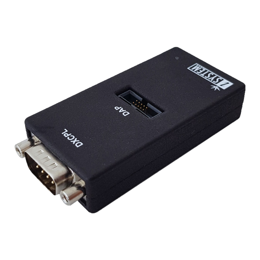
Page 6: Operation
Operation Device overview Device description A – DAP connector Pinout valid on the DAP connector side: Signal direction Signal Signal Signal direction Vref DAP connector pinout Signal direction definition: O – Output from the Active Probe to the target microcontroller I –... - Page 7 C – The LED indicator provides the status of the hardware as follows: Green – Powered on · Red – Power supply issue (e.g., burnt fuse · D – USB-C cable which is connected to the PC USB port. CAN 120 Ohm terminating resistor is not implemented on the DAP over CAN Physical Layer Converter.
-
Page 8: Winidea Configuration
1. Open Hardware menu / CPU Options. 2. Navigate to the SoC page. 3. Select DXCPL from the Debug channel Mode drop-down. 4. Confirm and establish the debug connection. Refer to isystem.com/connect for more information on how to connect and configure the hardware. -
Page 9: Accessories
Accessories DAP over CAN Physical Layer Converter is used together with the following iSYSTEM hardware: Ordering Code Description IC57000 iC5700 BlueBox IC57163 Infineon DAP/DAPE Active Probe IC57164 Infineon AGBT Active Probe IASAM22TRICOREPIN 10-pin 1.27 mm DAP Adapter (Infineon AGBT Active Probe) BB-FNET-100 1.0m FNet Cable (Active Probe) -
Page 10: User Notes
User Notes This page is intentionally left blank. -
Page 11: User Notes
User Notes This page is intentionally left blank. - Page 12 Whilst iSYSTEM reserves the right to make changes to its products and/or the specifications detailed herein, it does not make any representations or commitments to update this document.
Need help?
Do you have a question about the IEA-DXCPL and is the answer not in the manual?
Questions and answers