Table of Contents
Advertisement
Quick Links
Advertisement
Table of Contents

Related Manuals for Armfield S1


Summary of Contents for Armfield S1
- Page 1 Drainage and Seepage Tank Instruction Manual ISSUE 16 June 2013...
-
Page 2: Table Of Contents
Table of Contents Copyright and Trademarks ..................1 General Overview ....................... 2 Equipment Diagrams....................4 Important Safety Information..................6 Introduction......................6 Electrical Safety....................... 6 Water Borne Hazards ....................7 Description ........................8 Overview........................8 Drainage and Seepage Tank................... 8 Permeable Medium (Sand)..................8 Accessories supplied.................... - Page 3 Table of Contents Routine Maintenance ....................18 Responsibility ......................18 General........................18 Laboratory Teaching Exercises................. 19 Index to Exercises ....................19 General Comments ....................19 Basic Theory......................20 Exercise A - Seepage Underneath a Sheet Pile Wall ..........26 Exercise B - Seepage Through an Earth Dam............29 Exercise C - Draining Effect of a Tile Line ..............
-
Page 5: Copyright And Trademarks
Disclaimer This document and all the information contained within it is proprietary to Armfield Limited. This document must not be used for any purpose other than that for which it is supplied and its contents must not be reproduced, modified, adapted, published, translated or disclosed to any third party, in whole or in part, without the prior written permission of Armfield Limited. -
Page 6: General Overview
The class of problems involving flow of water through permeable media has a wide range and is of considerable importance to engineers and scientists. The Armfield Drainage and Seepage Tank, Model S1, facilitates a detailed study of the movement of water through permeable media. - Page 7 To further simplify the problem, we usually restrict ourselves to a two-dimensional flow, investigating conditions in a vertical cross section* along the horizontal direction of the moving water mass. The Armfield Drainage and Seepage Tank, Model S1, is specifically designed to permit the simulation in the laboratory of such vertical cross sections.
-
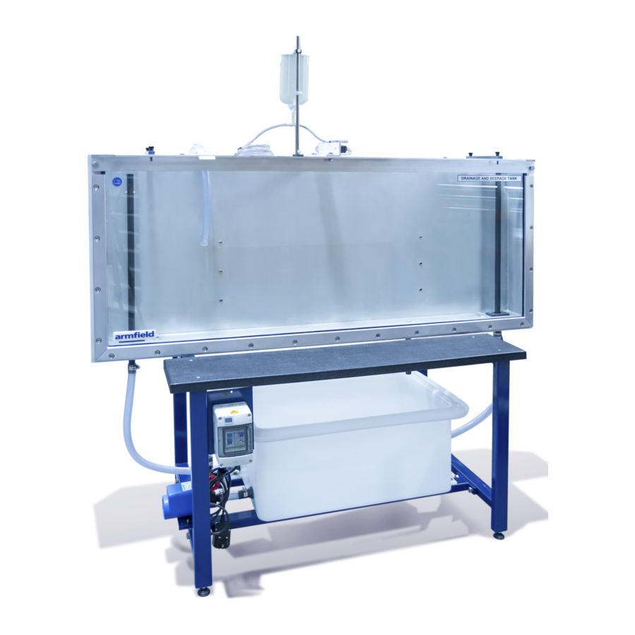
Page 8: Equipment Diagrams
Equipment Diagrams Figure 1: Front View of S1 Drainage and Seepage Tank (Shown with impermeable baffle fitted but not filled with sand) - Page 9 Equipment Diagrams Figure 2: Side View of S1 Drainage and Seepage Tank...
-
Page 10: Important Safety Information
Armfield then the protection provided by the equipment may be impaired. The S1 is a heavy piece of equipment, and should be lifted fork lift if possible. Ensure that the arms of the fork lift do not foul the sump moulding in the base of the unit. Do not attempt to lift the unit when it is full of sand or water. -
Page 11: Water Borne Hazards
Important Safety Information Water Borne Hazards The equipment described in this instruction manual involves the use of water, which under certain conditions can create a health hazard due to infection by harmful micro-organisms. For example, the microscopic bacterium called Legionella pneumophila will feed on any scale, rust, algae or sludge in water and will breed rapidly if the temperature of water is between 20 and 45°C. -
Page 12: Description
Description Where necessary, refer to the drawings in the Equipment Diagrams section. Overview After filling the sand tank with appropriate sand (not supplied) and filling the sump tank with water the equipment provides a self contained facility for the study of flow through permeable media. -
Page 13: Accessories Supplied
Description Accessories supplied The following accessories are supplied for use with S1: Foundation Pressure Plate Straight Permeable Membrane (x2) Curved Permeable Membrane Lateral Pressure Plate Tile Drain (x2) Dye Injection Unit This consists of a dye reservoir that is mounted on a metal rod clamped to the top rail of the sand tank as shown below. -
Page 14: Permeable Membranes
Curved Permeable Membrane Straight Permeable Membrane Two straight and one curved membrane are supplied with S1. Both membranes are formed from perforated sheet metal that is covered with fine woven material with perforations small enough to prevent the passage of sand particles. Rubber strips on the sides seal the membranes to the vertical front and rear walls of the sand tank. -
Page 15: Impermeable Membranes For Pressure Measurement
Description Impermeable Membranes for Pressure Measurement Foundation Pressure Plate Lateral Pressure Plate Both plates are made of 6mm thick PVC sheet and have rubber sealing strips along the edges. The foundation pressure plate is 610mm long with 5 Perspex tubes 210mm long normal to the surface, as standpipes. -
Page 16: Tile Drain
Armfield Instruction Manual Tile Drain Two tile drain assemblies are supplied for demonstration of dewatering using the tile drain technique. The tile drains can be used independently or in combination as required. Tile Drain Each drain consists of an 8mm internal diameter copper tube, with one end closed and having a pattern of eighteen holes drilled along its 150mm length. -
Page 17: Installation
Safe use of the equipment depends on following the correct installation procedure. Electrical Supply Electrical Supply for Version S1-A The equipment requires connection to a single phase, fused electrical supply. The standard electrical supply for this equipment is 230 V, 50 Hz. Check that the voltage and frequency of the electrical supply agree with the label attached to the supply cable on the equipment. -
Page 18: Installing The Equipment
Armfield Instruction Manual Installing the Equipment This item is supplied as one major assembly, together with all accessories listed above. After careful removal from the packing case it should be positioned on a suitable floor with adequate access space on all sides. -
Page 19: Operation
Operation Operating the Equipment See the Laboratory Teaching Exercises for details on operating the equipment. -
Page 20: Equipment Specifications
Equipment Specifications Overall Dimensions Length - 1.60m Width - 0.60m Height - 1.45m Sand Tank Dimensions Length - 1.50m Width - 0.10m Height - 0.60m Circulating Pump Duty at 50 Hz: 35 l/min maximum flow 2.2m maximum head Duty at 60 Hz: 33 l/min maximum flow 3.3m maximum head Drive: Magnetic coupling... - Page 21 Equipment Specifications c. Temperature 5°C to 40°C; d. Maximum relative humidity 80% for temperatures up to 31°C, decreasing linearly to 50% relative humidity at 40°C; e. Mains supply voltage fluctuations up to ±10% of the nominal voltage; Transient over-voltages typically present on the MAINS supply; Note: The normal level of transient over-voltages is impulse withstand (over- voltage) category II of IEC 60364-4-443;...
-
Page 22: Routine Maintenance
Routine Maintenance Responsibility To preserve the life and efficient operation of the equipment it is important that the equipment is properly maintained. Regular maintenance of the equipment is the responsibility of the end user and must be performed by qualified personnel who understand the operation of the equipment. -
Page 23: Laboratory Teaching Exercises
Laboratory Teaching Exercises Index to Exercises Exercise A - Seepage Underneath a Sheet Pile Wall Exercise B - Seepage Through an Earth Dam Exercise C - Draining Effect of a Tile Line Exercise D - Draining Effect of an Open Trench Exercise E - Uplift Pressure on Foundation of Structures Exercise F - Changing Uplift Pressure by Changing Length of Flow Lines Exercise G - Reduction of Uplift Pressure by Draining... -
Page 24: Basic Theory
Armfield Instruction Manual Basic Theory a. Darcy's Law The flow of water through porous media is governed by what is known as Darcy's Law: "The flow rate through porous media is proportional to head loss and inversely proportional to the length of the flow path". - Page 25 Laboratory Teaching Exercises Figure i For the purpose of classifying various types of soil with respect to permeability it has been found convenient to make use of a so-called, "laboratory (ie. 'standard') coefficient of permeability" designated as K. K is defined as the flow of water at 60 deg F in gallons per day through a one- square-foot cross sectional area of the soil in question under an hydraulic gradient of one foot per foot.
- Page 26 Armfield Instruction Manual water. The soil through which the water is pushed by the pressure head resists its movement in much the same manner, as a rough surface resists, or brakes, the movement of a sliding body. The soil resistance to moving water is called viscous friction since it causes a gradual dissipation of the kinetic energy in the moving water.
- Page 27 Laboratory Teaching Exercises Such a system of flow lines and equipotential lines is what is called the flow net. In each flow net, the flow lines and the equipotential lines intersect at right angles. This important feature of a flow net can be explained as follows. Just as water flowing downhill naturally follows the steepest path, so does water flowing between equipotential lines follow the path of maximum gradient.
- Page 28 Armfield Instruction Manual For the subsequent "square" area dF' the discharge is dq' = Kdh' …. (6) However, we can get only as much water into dF' as has passed through dF. There is simply no other place from which the water could come. Nor is there any other place where the water from dF could go.
- Page 29 Laboratory Teaching Exercises d. Boundary Conditions Figure iii If the conditions at all points of the boundary of the cross section of a soil mass are fixed and clearly defined, the flow net is uniquely determined. An example of such a case is represented by the situation shown in Figure ii. Here the bottoms of basin I and II represent two equipotential lines, the perimeter of the soil mass along the two walls and the bottom of the tank represents one flow line, and the perimeter of the part of the impermeable...
-
Page 30: Exercise A - Seepage Underneath A Sheet Pile Wall
Exercise A - Seepage Underneath a Sheet Pile Wall Objective Seepage underneath a sheet pile wall is one of the seepage problems that are most common in practice. Sheet pile walls are used to reduce seepage under all types of dams, sea walls, dividing walls, lock walls, coffer-dams and similar structures. - Page 31 Exercise A maintain constant water level in the upstream pool (in this case there will be a small continuous overflow from the upper pool). Smooth out any sharp irregularities of the sand bed which may have formed while filling the pool. Fix the bottle with dye on the stand in such a position that the liquid level is approximately at the same elevation as the water level in the upper pool.
- Page 32 Armfield Instruction Manual intersect all the experimental flow lines at right angles. Then flow lines are interpolated between the experimental ones so as to form, with the equipotential lines, a square network. Since the "channels" near the boundary flow lines need not be square at the first trial, the whole flow net may be adjusted.
-
Page 33: Exercise B - Seepage Through An Earth Dam
Exercise B - Seepage Through an Earth Dam Objective A frequently encountered type of seepage in hydraulic engineering is seepage through an earth dam. The term "earth dam" includes dams constructed from materials ranging from rock-fill to silt and clay. The services earth dams render are not limited to the impounding of water as in a reservoir. - Page 34 Armfield Instruction Manual upstream water level should be stabilised 25mm below the dam crest; the downstream level about 12mm above the bottom. After the dam segment has been formed, water is first poured into the downstream pool. Only after it is full should the upstream pool be filled. The rate of filling should be slow.
-
Page 35: Exercise C - Draining Effect Of A Tile Line
Exercise C - Draining Effect of a Tile Line Objective Tile lines, horizontal galleries, trenches and, sometimes, vertical wells are widely used to control seepage of water through permeable soils. This type of control differs in principle from control achieved by sheet pile walls. Sheet pile walls control by elongating the flow lines so as to reduce the hydraulic gradient and, hence, the seepage. - Page 36 Armfield Instruction Manual The space in the tank between the perforated metal sheets is then filled with sand to a depth of about 450mm. The overflows are set with their tops about 25mm above sand level, before water is poured slowly into the space around the upstream overflow.
-
Page 37: Exercise D - Draining Effect Of An Open Trench
Exercise D - Draining Effect of an Open Trench Objective Exercise C - Draining Effect of a Tile Line. Equipment Set Up In this experiment we simulate the drainage effect of a trench along one of its walls. We assume that the trench is in homogeneous material so that all dimensions and the flow pattern are symmetrical with respect to the centre line of the trench which will be represented by the downstream end wall of the tank. -
Page 38: Exercise E - Uplift Pressure On Foundation Of Structures
Exercise E - Uplift Pressure on Foundation of Structures Objective Whenever a structure (dam, weir, retaining wall, etc.) is built on permeable material and separates two water pools with different elevations of water level, seepage occurs underneath and the water exerts pressure on the structure along its whole submerged perimeter. -
Page 39: Exercise F - Changing Uplift Pressure By Changing Length Of Flow Lines
Exercise F - Changing Uplift Pressure by Changing Length of Flow Lines The pressure at any point along a flow line, and for that matter, pressure at any point along the submerged perimeter of a structure, changes with any change of the overall length of the flow line. -
Page 40: Exercise G - Reduction Of Uplift Pressure By Draining
Exercise G - Reduction of Uplift Pressure by Draining Objective If we want to reduce uplift pressure but are not interested in reducing the rate of seepage at the same time, the most convenient way to do it is by using a downstream drain in the form of a tile line or a trench. -
Page 41: Exercise H - Reduction Of Lateral Thrust On A Retaining Wall By Draining
Exercise H - Reduction of Lateral Thrust on a Retaining Wall by Draining Objective If water collected behind a retaining wall has no outlet, its hydrostatic pressure contributes to the lateral thrust of the soil and increases the total pressure load on the wall. - Page 42 Armfield Instruction Manual Another perforated metal sheet is placed at the upstream overflow pipe as in Exercise C - Draining Effect of a Tile Line. Now the space between the two perforated sheets is filled with sand up to about 50mm below the top of the tank.
-
Page 43: Exercise J - Quicksand
Exercise J - Quicksand Objective Quicksand develops when, in a saturated mass of sand, the uplift pressure reaches the weight of the sand body. The sand then starts to "float" and loses all its natural stability. It frequently occurs at the bottom of wells and downstream of engineering structures serving as water dams. - Page 44 Armfield Instruction Manual conditions of "quick" and if some object, a concrete or steel cube, for instance, is placed on its top it will sink since the sand is floating and does not have any stability.
-
Page 45: Exercise K - Stability Of An Earth Dam
Exercise K - Stability of an Earth Dam Objective The continuing safety of an earth dam structure depends on the stability of its slopes. The stability of the slope is in turn dependent on: 1. the properties of the material of which the dam is constructed; 2. - Page 46 Armfield Instruction Manual surface and so contributes to its stability. Downstream it acts to "pull" the sand more- or-less horizontally out of the dam. The process continues gradually until the upper part of the dam loses stability and collapses. Then the whole process starts again and proceeds upwards to the dam...
-
Page 47: Exercise L - Well Draining
Exercise L - Well Draining Objective A deep excavation for the construction of a foundation or other below ground activity, will frequently penetrate below the normal level for the water table in that area. If the works are in permeable ground and suitable measures are adopted, the excavation will fill with water to the local water table level. - Page 48 Armfield Instruction Manual Dye is then introduced as in Exercise C - Draining Effect of a Tile Line. The pump connected to the PVC clear tube is then operated and the inlet feed water adjusted to give a balanced water table level around the overflow.
-
Page 49: Contact Details For Further Information
Contact Details for Further Information Main Office: Armfield Limited Bridge House West Street Ringwood Hampshire England BH24 1DY Tel: +44 (0)1425 478781 Fax: +44 (0)1425 470916 Email: sales@armfield.co.uk support@armfield.co.uk Web: http://www.armfield.co.uk US Office: Armfield Inc. 9 Trenton - Lakewood Road...
Need help?
Do you have a question about the S1 and is the answer not in the manual?
Questions and answers