Table of Contents
Troubleshooting

Subscribe to Our Youtube Channel
Related Manuals for COBHAM DIGImini Series


Summary of Contents for COBHAM DIGImini Series
- Page 1 DIGImini EMEA/APAC/AUSTRALIA Digital Multi-band Series User Manual – 00030UMCD Rev. 5.0 The most important thing we build is trust Cobham Wireless – Coverage Date: 11-Oct-15 www.cobham.com/wireless Document number: 00030UMCD Rev. 5.0 Page | I...
- Page 2 Dual Band DIGImini 700/1800, DIGImini 900/2100, DIGImini 1800/2600, DIGImini 900/1800 DIGImini 1800/2100, DIGImini 850/1800, DIGImini 850/2100 D-MINI 4B-AK Quad-band DIGImini 4 bands Accessory upgrade kit www.cobham.com/wireless Date: 11-Oct-15 Cobham Wireless – Coverage Page | II Rev. 5.0 Document number: 00030UMCD...
- Page 3 However, Cobham Wireless assumes no responsibility for its use. In no event shall Cobham Wireless be liable for any damage resulting from loss of data, loss of use, or loss of profits and Cobham Wireless further disclaims any and all liability for indirect, incidental, special, consequential or other similes damages.
- Page 4 Always observe standard safety precautions during installation, operation and maintenance of this product. Exclusive Remedies The remedies provided herein are the Buyer’s sole and exclusive remedies. Cobham Wireless shall not be viable for any direct, incidental, or consequential damages, whether based on contract, tort, or any legal theory. www.cobham.com/wireless Date: 11-Oct-15 Cobham Wireless –...
- Page 5 Caution: Safety to Cobham Wireless assumes no liability for the customer's failure to comply with equipment these precautions. This entire manual should be read and understood before operating or maintaining the repeater.
- Page 6 This applies to European products that support 2100Mhz. These type of products are Class 2. This band can also be used by fixed service on a national basis. www.cobham.com/wireless Date: 11-Oct-15 Cobham Wireless – Coverage Page | VI Rev. 5.0...
-
Page 7: Table Of Contents
4.4.1 Middle layer Items ..................... 4-4 4.4.2 Bottom Layer Items ....................4-4 4.4.3 Additional Items ......................4-5 4.4.4 4.5 Upgrading to a Quad-Band System..................4-5 Cobham Wireless – Coverage Date: 11-Oct-15 www.cobham.com/wireless Page | VII Document number: 00030UMCD Rev. 5.0... - Page 8 Appendix B: EGSM 900 Frequency VS Channel Number ............1 Appendix C: GSM 1800 Freq VS Channel Number ..............1 Appendix D: Declarations of Conformity ................1 www.cobham.com/wireless Cobham Wireless – Coverage Date: 11-Oct-15 Page | VIII Document number: 00030UMCD...
-
Page 9: System Description
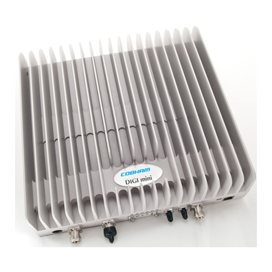
GUI. Remote management is done via optional wireless modem. With the Cobham Wireless advanced supervision and control software -AEM, the entire fleet of digital multiband repeaters can be monitored. Figure 1-1. Cobham Wireless DIGImini Repeater Cobham Wireless –... -
Page 10: Features And Capabilities
(supports SNMP traps) or connection to an external modem. * * Upgrade options for single-band to dual-band software upgrade and for remote monitoring (Ethernet network or external modem) are implemented using two different licenses. www.cobham.com/wireless Date: 11-Oct-15 Cobham Wireless – Coverage Page | 1-2 Rev. 5.0 Document number: 00030UMCD... -
Page 11: Models And Ordering Information
1.4 Single Band Unit Upgradeable to Dual-band Single-band units can be upgraded to support two bands by acquiring the appropriate license file from Cobham Wireless support team. 1.5 Smart-ALC Function The Smart Automatic Level Control (Smart-ALC) is an innovative algorithm for automatic repeater gain adjustment per sub-band. -
Page 12: Dmcu - Optional
An optional DMCU supporting an external modem is also connected externally, where a single DMCU can serve two cascaded units. front side The interfaces are located on the and on the panels. www.cobham.com/wireless Date: 11-Oct-15 Cobham Wireless – Coverage Page | 1-4 Rev. 5.0 Document number: 00030UMCD... -
Page 13: Front Panel Interfaces
Downlink path status and RSSI indication: (e.g. 850, 1900, etc) Relevant only if connected to DMCU: CCD Operation status MODEM Relevant only if connected to DMCU: DMCU Modem operation status Cobham Wireless – Coverage Date: 11-Oct-15 www.cobham.com/wireless Page |1-5 Document number: 00030UMCD... -
Page 14: Side Panel Interfaces
DIGImini units are cascaded. Otherwise, it is preassembled. Connect to Front panel DC power Connect to 110/240 (12V) connector VAC power source Figure 1-4: Repeater Power Supply www.cobham.com/wireless Date: 11-Oct-15 Cobham Wireless – Coverage Page | 1-6 Rev. 5.0 Document number: 00030UMCD... -
Page 15: Antenna And Repeater Installation Requirements
Verify that the antenna is in the base stations line of sight (raise the antenna if necessary). • Install the donor antenna at a higher level (i.e. floor) than the mobile antenna. Must be installed at a minimum distance of 20cm from any personnel within the area. • Cobham Wireless – Coverage Date: 11-Oct-15 www.cobham.com/wireless... -
Page 16: Service Antenna Requirements
Install the Service Antenna at the designated height and tune it roughly toward the Service • coverage area. • Installation of this antenna must provide a minimum separation distance of 20cm from any personnel within the area. www.cobham.com/wireless Date: 11-Oct-15 Cobham Wireless – Coverage Page | 2-2 Rev. 5.0 Document number: 00030UMCD... -
Page 17: Repeater Pre-Installation Requirements
All cables shall be weather-resistant type • Cable length - determined by the Repeater installation plan. When calculating the cable length, take into account excess cable slack so as not to limit the insertion paths. Cobham Wireless – Coverage Date: 11-Oct-15 www.cobham.com/wireless... -
Page 19: Single Unit Repeater Installation
3.2 Required Tools and Materials The following is required in order to install the Repeater: • Standard professional tool box A computer (i.e. laptop for running the setup) • Cobham Wireless – Coverage Date: 11-Oct-15 www.cobham.com/wireless Page | 3-1 Document number: 00030UMCD... -
Page 20: Digimini Single Unit Kit
1. Examine the shipping container for damage before unpacking the unit. 2. Perform a visual inspection to reveal any physical damage to the equipment. 3. Verify that all of the equipment (listed below) is included. Otherwise contact Cobham Wireless. DIGImini Repeater Kit... -
Page 21: Mounting The Repeater
2. Hang the bracket on the wall. Location of Location of assembly holes assembly holes Figure 3-1. Mounting the Bracket on the Wall Cobham Wireless – Coverage Date: 11-Oct-15 www.cobham.com/wireless Page |3-3 Document number: 00030UMCD... - Page 22 Fit two BOTTOM Repeater bolts on bracket slots and lift UP to slide two TOP screws into top slots Connectors down Figure 3-3. DIGImini to Bracket Mounting www.cobham.com/wireless Date: 11-Oct-15 Cobham Wireless – Coverage Page | 3-4 Rev. 5.0 Document number: 00030UMCD...
-
Page 23: Before Connecting The Antennas Or Power
Before connecting the antennas or power perform the following procedures described in this section: Verify isolation between the donor and mobile antennas • Verify link between the BTS and the Repeater • Cobham Wireless – Coverage Date: 11-Oct-15 www.cobham.com/wireless Page |3-5 Document number: 00030UMCD Rev. -
Page 24: Verifying Donor And Service Antennas Isolation
Antenna connector or antenna cable faulty Line-of-sight problem (obstruction), etc. • 4. Register the signal strength of the downlink channel for the system operation phase. www.cobham.com/wireless Date: 11-Oct-15 Cobham Wireless – Coverage Page | 3-6 Rev. 5.0 Document number: 00030UMCD... - Page 25 3. Connect the Service antenna to the Repeater MOBILE port. (Mobile antenna specifications and installation criteria are described in section 2.2). 4. Verify all RF connectors are tightened and the cables and antennas are secured. Base Mobile Figure 3-5. Antenna Connections Cobham Wireless – Coverage Date: 11-Oct-15 www.cobham.com/wireless Page |3-7 Document number: 00030UMCD Rev.
-
Page 26: Power Up
DIGImini Control Unit (DMCU) – continue to Chapter 5 - SETUP AND • CONFIGURATION. with • Installations DMCU – refer to the DMCU User Manual. www.cobham.com/wireless Date: 11-Oct-15 Cobham Wireless – Coverage Page | 3-8 Rev. 5.0 Document number: 00030UMCD... -
Page 27: Quad-Band Repeater Installation
7. Perform the required isolation and link tests. 8. Connect the antennas. 9. Power-on the Repeater. 10. For installations with a DMCU, mount the unit and refer to the DIGImini Single/Dual Band user manual for detailed instructions. Cobham Wireless – Coverage Date: 11-Oct-15 www.cobham.com/wireless... -
Page 28: View Of The Dual Unit Installation
Standard professional tool box • • A computer (i.e. laptop for running the setup) – refer to the single/dual band user manual for setup and commissioning procedure. www.cobham.com/wireless Date: 11-Oct-15 Cobham Wireless – Coverage Page | 4-2 Rev. 5.0 Document number: 00030UMCD... -
Page 29: Digimini Tri/Quad-Band Kit
2. Perform a visual inspection to reveal any physical damage to the items. 3. Verify that all of the items are included in the relevant layer as described. Otherwise contact Cobham Wireless. 4.4.1 Top Layer Items X2 Long Coupling SMA... -
Page 30: Middle Layer Items
Type 2 RF Combiner Figure 4-4. Quad-Band Kit -Middle Layer items 4.4.3 Bottom Layer Items 2 x Expansion, Side Brackets Figure 4-5. Quad-Band Kit-Bottom Layer Items www.cobham.com/wireless Date: 11-Oct-15 Cobham Wireless – Coverage Page | 4-4 Rev. 5.0 Document number: 00030UMCD... -
Page 31: Upgrading To A Quad-Band System
NOTE: If holes are to be drilled, use the bracket to mark the hole locations prior to the following assembly procedure. Follow the (wallmount) bracket mounting instructions in 3.4 - Mounting the Repeater. • • Continue to following Step 3. Cobham Wireless – Coverage Date: 11-Oct-15 www.cobham.com/wireless Page |4-5 Document number: 00030UMCD Rev. - Page 32 Bracket edge folding over – AWAY from X2 holes facing combiner this direction Figure 4-6. Left bracket - Combiner and Spacer Secured to Side Cascading Bracket www.cobham.com/wireless Date: 11-Oct-15 Cobham Wireless – Coverage Page | 4-6 Rev. 5.0 Document number: 00030UMCD...
- Page 33 Secure Loosely on each side – but enough to hold when assembly is picked up Figure 4-7. Assemble Side Brackets on Bottom Repeater Cobham Wireless – Coverage Date: 11-Oct-15 www.cobham.com/wireless Page |4-7 Document number: 00030UMCD...
- Page 34 6. Remove the LED plates of BOTH Repeaters and set them aside. Unscrew and remove plates Figure 4-9. Removing Dedicated Tabs Unscrew and remove plates www.cobham.com/wireless Date: 11-Oct-15 Cobham Wireless – Coverage Page | 4-8 Rev. 5.0 Document number: 00030UMCD...
- Page 35 SIDE of the repeater. (e.g for DIGImini 900/2100, “Band 1” is 900 and “Band 2” is 2100). Plate covering flat cable Figure 4-11. Assembling Interconnecting Cover Plate Cobham Wireless – Coverage Date: 11-Oct-15 www.cobham.com/wireless...
-
Page 36: Choosing The Appropriate Plate
NOTE: The band frequencies represented by Band-1 and Band-2 are located at the side of the repeater. (e.g for DIGImini 900/2100, “Band 1” is 900 and “Band 2” is 2100). www.cobham.com/wireless Date: 11-Oct-15 Cobham Wireless – Coverage Page | 4-10 Rev. 5.0... - Page 37 Use the following tab and label type. Existing Plates on both New Quad-Band Plate and Label DIGImini Type II Units for DIGImini Type II Units Figure 4-14.Examples of Plate Used When Both Units are Type-II Cobham Wireless – Coverage Date: 11-Oct-15 www.cobham.com/wireless Page |4-11 Document number: 00030UMCD Rev.
- Page 38 NOTE: Assemble the label onto the plate; the relevant bands are on the side of the corresponding repeater. Type I Side Figure 4-15.Examples of Plate Used When Both Units are Type-I www.cobham.com/wireless Date: 11-Oct-15 Cobham Wireless – Coverage Page | 4-12 Rev. 5.0 Document number: 00030UMCD...
-
Page 39: Connect Sma Jumper Cables
2 to 2 Long (340mm) Connect between connectors labeled (i.e 3 to 3 Long (290mm) Connect between connectors labeled (i.e Mobile BASE Figure 4-16. DIGImini Quad-Band Jumper Connections Cobham Wireless – Coverage Date: 11-Oct-15 www.cobham.com/wireless Page |4-13 Document number: 00030UMCD Rev. 5.0... -
Page 40: Mount And Secure Quad-Band Assembly
• Tighten the loose screws on each side. Tighten screw on wall-side bracket Figure 4-17. Mount Quadband Assembly on Wallbracket www.cobham.com/wireless Date: 11-Oct-15 Cobham Wireless – Coverage Page | 4-14 Rev. 5.0 Document number: 00030UMCD... - Page 41 Figure 4-18. Insert Ties for Securing Power Supply Fit Power Supplies on ridge(s) on side of wallbracket. • • Secure the ties. AC/DC Converter PS Ties Figure 4-19. Secure Power Supply Cobham Wireless – Coverage Date: 11-Oct-15 www.cobham.com/wireless Page |4-15 Document number: 00030UMCD Rev. 5.0...
-
Page 42: Before Connecting The Antennas Or Power
4. Verify all RF connectors are tightened and the cables and antennas are secured. Service Antenna Donor Antenna Figure 4-20. Service and Donor Antenna Connections www.cobham.com/wireless Date: 11-Oct-15 Cobham Wireless – Coverage Page | 4-16 Rev. 5.0 Document number: 00030UMCD... -
Page 43: Power Up
• Installations DIGImini Control Unit (DMCU) – continue to Chapter 5 - SETUP AND CONFIGURATION with • Installations DMCU – refer to the DMCU User Manual. Cobham Wireless – Coverage Date: 11-Oct-15 www.cobham.com/wireless Page |4-17 Document number: 00030UMCD Rev. 5.0... -
Page 45: Setup And Configuration
The setup procedure consists of the following steps: 1. Open a local Web session to the Repeater. If you are not familiar with the Cobham Wireless Web Access application, it is recommended to quickly review the Navigating the Web GUI Application section. -
Page 46: Connect The Computer To The Repeater
The Web GUI will allow for configuration of both repeaters. Ethernet cross - cable Connect to either unit Figure 5-2: Cascaded DIGImini Quad-band www.cobham.com/wireless Date: 11-Oct-15 Cobham Wireless – Coverage Page | 5-2 Rev. 5.0 Document number: 00030UMCD... -
Page 47: Configure The Computer's Network Parameters
Choose Change Adapter Settings and select Local Area Connection. The Local Area • Connection Properties dialog appears. Select Internet Protocol Version 4 Figure 5-3 Networking Tab 2. In the Items list, double-click Internet Protocol Version 4 (TCP/IPv4). Cobham Wireless – Coverage Date: 11-Oct-15 www.cobham.com/wireless Page |5-3 Document number: 00030UMCD... - Page 48 Define the subnet mask as shown (255.255.255.0) Click OK. The computer communication parameters are now defined and you can open a • session to the Repeater. www.cobham.com/wireless Date: 11-Oct-15 Cobham Wireless – Coverage Page | 5-4 Rev. 5.0 Document number: 00030UMCD...
-
Page 49: Login To The Repeater
Note that both are case sensitive and must be entered with lower case letters. 4. Click Login. The application main window appears. 5. Quickly review the following section describing the application window and then proceed to configure the signal levels according to section 5.3. Cobham Wireless – Coverage Date: 11-Oct-15 www.cobham.com/wireless... -
Page 50: Navigating The Web Gui Application
Buttons Tabs related to selected Tree item Topology Tree Items Pane related to selected tree item Figure 5-7. Example of Web GUI Screen (shows dual-band) www.cobham.com/wireless Date: 11-Oct-15 Cobham Wireless – Coverage Page | 5-6 Rev. 5.0 Document number: 00030UMCD... -
Page 51: Band Pane And Tabs
This section provides a description of the RF Gain setting criteria (set via the Controls and Params Pane), the criteria determining the number of available bands and a step-by-step procedure of the signal level and channel configuration procedure. Cobham Wireless – Coverage Date: 11-Oct-15 www.cobham.com/wireless... -
Page 52: Rf Gain Setting Criteria
(in 200KHz steps) 850MHz, 900MHz, 1800MHz 10 to 25 MHz ( in 200KHz steps) 850MHz, 900MHz, 2100MHz WCDMA 5, 10MHz 850MHz, 900MHz, 2100MHz WCDMA 15, 20, 25MHz www.cobham.com/wireless Date: 11-Oct-15 Cobham Wireless – Coverage Page | 5-8 Rev. 5.0 Document number: 00030UMCD... -
Page 53: Adjusting The Signal Levels And Configuring Channels
Bandwidth - start and stop frequency - see appendices B and C for parallel GSM channels. • • Maximum power Maximum gain • • Gain delta The defined sub-bands are displayed in the lower part of the screen for reference. Cobham Wireless – Coverage Date: 11-Oct-15 www.cobham.com/wireless Page |5-9 Document number: 00030UMCD Rev. 5.0... - Page 54 DL Output Threshold Delta (dB) - the delta from the set Composite Output Power, below which the alarm 'Donor power is too low' is activated. www.cobham.com/wireless Date: 11-Oct-15 Cobham Wireless – Coverage Page | 5-10 Rev. 5.0 Document number: 00030UMCD...
- Page 55 UL Gain Δ - used for noise control. Sets the difference between UL and DL gain. UL Measured Ch. Gain - measured UL Gain (dB) for the selected sub-band. • 7. Click Send (top window area option). Cobham Wireless – Coverage Date: 11-Oct-15 www.cobham.com/wireless...
- Page 56 Alarms are generated: Click the Alarms tab • • Verify that all the indicators are GREEN in the Alarms tab Figure 5-10. Example of Alarms Tab www.cobham.com/wireless Date: 11-Oct-15 Cobham Wireless – Coverage Page | 5-12 Rev. 5.0 Document number: 00030UMCD...
-
Page 57: Administration, Monitoring And Troubleshooting
NOTE: Each feature is implemented using a DEDICATED license file. To upload a license file 1. Contact your Cobham Wireless service representative and purchase the option. NOTE: You will be required the System ID listed in the Band Info tab (section 5.3.2.2). -
Page 58: Dual-Band Support
6.1.1. The second band will be displayed in the Topology Tree and the relevant tabs will be updated in the display area. www.cobham.com/wireless Date: 11-Oct-15 Cobham Wireless – Coverage Page | 6-2 Rev. 5.0 Document number: 00030UMCD... -
Page 59: Connection To An Ethernet Network
NOTE: By default, a trap will be sent if a Heartbeat signal is not detected for 60 minutes. The heartbeat period may be modified or disabled (set to ‘0’). 4. Click Send. 5. Connect the unit Ethernet port to the network. Cobham Wireless – Coverage Date: 11-Oct-15 www.cobham.com/wireless... -
Page 60: Connection To An External Modem
If the Modem IP Address is 192.168.1.10 192.168.1.10 Then set the Repeater Local Gateway to 5. Click Send. 6. Connect the unit Ethernet port to the external modem. www.cobham.com/wireless Date: 11-Oct-15 Cobham Wireless – Coverage Page | 6-4 Rev. 5.0 Document number: 00030UMCD... -
Page 61: Monitoring And Troubleshooting
RED and GREEN LEDs are available. Color Description Green Warning. Does not require immediate action Yellow Major. Higher priority, requires user attention Orange Critical. Requires user’s immediate action Cobham Wireless – Coverage Date: 11-Oct-15 www.cobham.com/wireless Page |6-5 Document number: 00030UMCD Rev. 5.0... - Page 62 Fault and most probable cause and Recommendation Built In Test Description: Self test. Possible causes: Hardware failure, Circuitry failure, Software failure Recommended action: Wait 12 hours before contacting Cobham Wireless Support Temperature Description: High temperature indicated Possible causes: Unit temperature becomes high due to excessive heat.
-
Page 63: Digimini Led Troubleshooting
Green Steady - modem is either not defined, or defined modem is operating normally. • Orange Steady– modem is trying to connect • Red Steady– modem failed to connect Cobham Wireless – Coverage Date: 11-Oct-15 www.cobham.com/wireless Page |6-7 Document number: 00030UMCD... -
Page 65: Appendix A: Specifications
Noise figure @ max gain Propagation delay 6 μsec 6 μsec Number of filters per band* Up to 8 Up to 8 Continued on the next page…. Cobham Wireless – Coverage Date: 11-Oct-15 www.cobham.com/wireless Page |B- 1 Document number: 00030UM Rev. 5.0... - Page 66 25MHz bandwidth) ** Combining 850MHz and 900MHz bands together may require using external filters. *** To pass the ACMA requirement on 2600MHz composite power should be reduced by 3dB (17dBm) www.cobham.com/wireless Cobham Wireless – Coverage Date: 11-Oct-15 Page | A-2 Document number: 00030UMCD Rev.
-
Page 67: Appendix B: Egsm 900 Frequency Vs Channel Number
928.8 1020 889.2 934.2 1021 889.4 934.4 884.2 929.2 1022 889.6 934.6 884.4 929.4 1023 889.8 934.8 884.6 929.6 1024 884.8 929.8 1000 885.2 930.2 Cobham Wireless – Coverage Date: 11-Oct-15 www.cobham.com/wireless Page |B- 1 Document number: 00030UMCD Rev. 5.0... - Page 68 950.4 897.2 942.2 905.6 950.6 897.4 942.4 905.8 950.8 897.6 942.6 897.8 942.8 906.2 951.2 906.4 951.4 898.2 943.2 906.6 951.6 898.4 943.4 906.8 951.8 www.cobham.com/wireless Cobham Wireless – Coverage Date: 11-Oct-15 Page | B-2 Document number: 00030UMCD Rev. 5.0...
- Page 69 956.8 912.2 957.2 912.4 957.4 912.6 957.6 912.8 957.8 913.2 958.2 913.4 958.4 913.6 958.6 913.8 958.8 914.2 959.2 914.4 959.4 914.6 959.6 914.8 959.8 Cobham Wireless – Coverage Date: 11-Oct-15 www.cobham.com/wireless Page |B- 3 Document number: 00030UMCD Rev. 5.0...
-
Page 71: Appendix C: Gsm 1800 Freq Vs Channel Number
1722.6 1817.6 1716 1811 1722.8 1817.8 1716.2 1811.2 1723 1818 1716.4 1811.4 1723.2 1818.2 1716.6 1811.6 1723.4 1818.4 1716.8 1811.8 1723.6 1818.6 1800MHz ARFCN Table Cobham Wireless – Coverage Date: 11-Oct-15 www.cobham.com/wireless Page |C- 1 Document number: 00030UMCD Rev. 5.0... - Page 72 1833.4 1730.6 1825.6 1738.6 1833.6 1730.8 1825.8 1738.8 1833.8 1731 1826 1739 1834 1731.2 1826.2 1739.2 1834.2 1731.4 1826.4 1739.4 1834.4 1731.6 1826.6 1739.6 1834.6 www.cobham.com/wireless Date: 11-Oct-15 Cobham Wireless – Coverage Page | C-2 Rev. 5.0 Document number: 00030UMCD...
- Page 73 1849 1746.4 1841.4 1754.2 1849.2 1746.6 1841.6 1754.4 1849.4 1746.8 1841.8 1754.6 1849.6 1747 1842 1754.8 1849.8 1747.2 1842.2 1755 1850 1747.4 1842.4 1755.2 1850.2 Cobham Wireless – Coverage Date: 11-Oct-15 www.cobham.com/wireless Page |C- 3 Document number: 00030UMCD Rev. 5.0...
- Page 74 1863.8 1761.6 1856.6 1769 1864 1761.8 1856.8 1769.2 1864.2 1762 1857 1769.4 1864.4 1762.2 1857.2 1769.6 1864.6 1762.4 1857.4 1769.8 1864.8 1762.6 1857.6 1770 1865 www.cobham.com/wireless Date: 11-Oct-15 Cobham Wireless – Coverage Page | C-4 Rev. 5.0 Document number: 00030UMCD...
- Page 75 1878.6 1776.4 1871.4 1783.8 1878.8 1776.6 1871.6 1784 1879 1776.8 1871.8 1784.2 1879.2 1777 1872 1784.4 1879.4 1777.2 1872.2 1784.6 1879.6 1777.4 1872.4 1784.8 1879.8 Cobham Wireless – Coverage Date: 11-Oct-15 www.cobham.com/wireless Page |C- 5 Document number: 00030UMCD Rev. 5.0...
-
Page 77: Appendix D: Declarations Of Conformity
PRODUCT DESCRIPTION AND USER’S MANUAL Appendix D: Declarations of Conformity This section includes the following declarations of conformity: • 2011-50-3 • 2011-58-3 • 2013-29 2013-34 • Cobham Wireless – Coverage Date: 11-Oct-15 www.cobham.com/wireless Page |D- 1 Document number: 00030UMCD Rev. 5.0... - Page 78 DIGIMINI EMEA/APAC/AUSTRALIA REPEATERS PRODUCT DESCRIPTION AND USER’S MANUAL www.cobham.com/wireless Date: 11-Oct-15 Cobham Wireless – Coverage Page | D-2 Rev. 5.0 Document number: 00030UMCD...
- Page 79 DIGIMINI EMEA/APAC/AUSTRALIA REPEATERS PRODUCT DESCRIPTION AND USER’S MANUAL Cobham Wireless – Coverage Date: 11-Oct-15 www.cobham.com/wireless Page |D- 3 Document number: 00030UMCD Rev. 5.0...
- Page 80 DIGIMINI EMEA/APAC/AUSTRALIA REPEATERS PRODUCT DESCRIPTION AND USER’S MANUAL www.cobham.com/wireless Date: 11-Oct-15 Cobham Wireless – Coverage Page | D-4 Rev. 5.0 Document number: 00030UMCD...
- Page 81 DIGIMINI EMEA/APAC/AUSTRALIA REPEATERS PRODUCT DESCRIPTION AND USER’S MANUAL Cobham Wireless – Coverage Date: 11-Oct-15 www.cobham.com/wireless Page |D- 5 Document number: 00030UMCD Rev. 5.0...
Need help?
Do you have a question about the DIGImini Series and is the answer not in the manual?
Questions and answers