Advertisement
Quick Links
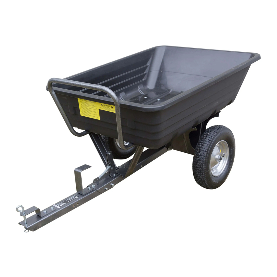
OPERATOR'S MANUAL & PARTS LIST
MODEL – THTPDC
650LB TOWED POLY DUMP CART
Spares & Support: 01793 333212
Please read & understand this manual, paying particular attention to the safety
instructions, before use.
The manufacturer reserves the right to change the product specification and
livery according to continued product improvements.
193845001
15/06/2015
Advertisement

Related Manuals for The Handy THTPDC


Summary of Contents for The Handy THTPDC
- Page 1 OPERATOR’S MANUAL & PARTS LIST MODEL – THTPDC 650LB TOWED POLY DUMP CART Spares & Support: 01793 333212 Please read & understand this manual, paying particular attention to the safety instructions, before use. The manufacturer reserves the right to change the product specification and livery according to continued product improvements.
-
Page 3: Table Of Contents
Assembly Is Required This product requires assembly before use. See the “Assembly” section for instructions. Because of the weight and size of the Trailer, it is recommended that a minimum of TWO adults be present to assist with the assembly. CONTENTS SPECIFICATIONS SAFETY INSTRUCTIONS... -
Page 4: Specifications
SPECIFICATIONS Model THTPDC Product Number 193845001 Load Capacity 650lb (295kg) Bed Dimensions (mm) (L)1025 x (W)765 x (H)275 Overall Dimensions (mm) (L)1550 x (W)870 x (H)690 Tyre Size 407mm (16”) Tyre Type Pneumatic Tyre PSI (Recommended/Maximum) 20 PSI/25 PSI (Do not exceed) -
Page 5: Safety Instructions
SAFETY INSTRUCTIONS Read and understand the owner’s manual and labels affixed to the machine. Learn its application and limitations as well as the specific potential hazards. Retain these instructions for future reference. The operator is responsible for following the warnings & instructions in this manual and on the product. -
Page 6: Operating Instructions
OPERATING INSTRUCTIONS WARNING – Before using the Trailer, review the below instructions & safety information within the manual. Failure to follow these instructions may result in property damage or injury to the operator or bystanders. 1. DO NOT at any time carry passengers. 2. -
Page 7: Maintenance & Storage
PUSH CART Important: Leave the latch lock clevis pin in place at all times while using the cart as a push cart. To convert the cart for push operation, remove the Ø13x98 long clevis pin and R Pin Ø3 which secure the draw bar in the towing position. -
Page 8: Assembly
ASSEMBLY Remove the hardware pack and all loose parts from the carton. Be sure the carton is empty before discarding. Insert the latch lock between the latch mount brackets and connect them using an M6x20 hex bolt and a M6 lock nut. Tighten so that the latch lock can still pivot. Attach the extension spring to the latch lock and the latch mount bracket as shown in figure 1. - Page 9 Lay draw bar B (open side facing up) onto the Wheel Support. Insert the axle through the wheel support and draw bar B. Draw Bar B Connect the hitch bracket to draw bar A, using two M8x20 hex bolts and M8 lock nuts. Tighten. ...
- Page 10 Place draw bar A, inside draw bar B as shown below. Fasten the draw bar sections together using an M10x95 hex bolt and a M10 lock nut. Tighten, leaving the nut just loose enough that the sections of the draw bar can pivot freely. ...
- Page 11 Turn the wheel support over to rest on the wheels. Place the Latch Stand Bracket onto the draw bar, sliding it underneath the Latch Lock. Place the Latch Stand Plate on top of the latch stand bracket. The tabs at the ends of the channels must face the rear. ...
- Page 12 Insert four flat head bolts M6x16 down through the tray and the inner holes in the Latch Stand Plate. Secure the bolts with four Ø6 big flat washers and M6 lock nuts. Do not fully tighten. Slide the handle into the channels in the Latch Stand Plate. Push the handle in all the way against the front of the tray depressing buttons in the bottom of the handle.
- Page 13 Rotate the Draw Bar A from underneath Draw Bar B, to the below extended Draw Bar image and secure with Clevis Pin’s Ø13X28 & Ø13X98 and Hex Bolt M10x20. Hex Bolt M10x20 Insert the hitch pin through the draw bar and hitch bracket and secure it with the Ø3 R Pin.
- Page 14 PARTS DIAGRAM...
- Page 15 PARTS LIST ITEM NO PART NO DESCRIPTION QTY ITEM NO PART NO DESCRIPTION TH180-1 Poly Tray TH180-19 Hex Bolt M6x20 TH180-2 Flat Head Bolt M8x16 TH180-20 Latch Mount Bracket (Right) TH180-3 Flat Head Bolt M6x16 TH180-21 Latch Lock TH180-4 Flat Washer Ø6 TH180-22 Lock Washer Ø6 TH180-5...
- Page 16 GJ HANDY & CO LTD USER WARRANTY POLICY 1. Users Statement of Warranty Each new machine is warranted against defective material or assembly of material under normal usage. The warranty applies to the original purchaser and covers faulty parts and the labour involved in replacing and repairing those parts, which are of original manufacture.
- Page 17 GJ HANDY & CO LTD USER WARRANTY POLICY 3. Not covered by this warranty The warranty policy does not cover any depreciation or damages caused by ordinary wear, rusting or corrosion, lack of correct maintenance or operation, misuse, abuse, lack of transportation or accident.
- Page 18 NOTES __________________________________________ __________________________________________ __________________________________________ __________________________________________ __________________________________________ __________________________________________ __________________________________________ __________________________________________ __________________________________________ __________________________________________ __________________________________________ __________________________________________ __________________________________________ __________________________________________ __________________________________________ __________________________________________ __________________________________________ __________________________________________ __________________________________________ __________________________________________ __________________________________________ __________________________________________ __________________________________________ __________________________________________ __________________________________________ __________________________________________ __________________________________________...
- Page 20 To order spare parts and see the complete range of garden machinery and garden equipment from Handy, visit: www.thehandy.co.uk Spares & Support: 01793 333212 This symbol on the product or on its packaging indicates that this product may not be treated as household waste. Instead it shall be handed over to the applicable collection point for the recycling of electrical and electronic equipment.
Need help?
Do you have a question about the THTPDC and is the answer not in the manual?
Questions and answers