Advertisement
Quick Links
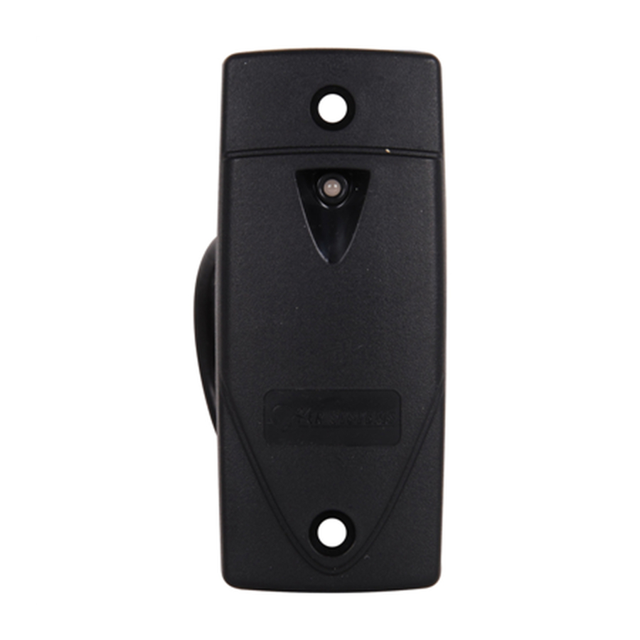
NXT-1RE/-3RE/-5RE Exit Reader
Installation Guide
Keri NXT controllers with Mercury firmware now provide an Entrance/Exit door control feature. This Entrance/Exit
feature allows two readers to be wired to one bus on the NXT controller to control entrance and exit through that one door.
Access requests entering through the door use a standard NXT-R Reader (designated as an Entrance Reader). Access
requests exiting through that same door use an NXT-RE Reader (designated as an Exit Reader). Otherwise, all
specifications and wiring information for the two reader types are identical.
NOTE: The Entrance/Exit Door reader feature is currently only available on NXT controllers using the optional, Mercury
Inside firmware. For NXT controllers using standard NXT firmware, a reader configured as an Out-door is not recognized
by the Doors.NET software.
1.0
Wiring and Layout Diagrams
1.1
NXT-1RE/-3RE/-5RE Exit Readers
An NXT Exit Reader is wired to a bus the same way a standard NXT Entrance Reader is wired, but both readers are wired
to the same bus. This can be done using two separate reader cables wired into the terminal block at the bus on the
controller, or by splicing the two readers together near the door and running one cable to the controller.
LED
Beeper
In Reader
LED
Beeper
Out Reader
On power up, an Exit Reader's LED will flash red, then green, then stay at amber.
This equipment has been tested and found to comply with the limits for a Class A digital device, pursuant to Part 15 of the FCC Rules.
•
These limits are designed to provide reasonable protection against harmful interference when the equipment is operated in a commercial
environment. This equipment generates, uses, and can radiate radio frequency energy and, if not installed and used in accordance with the
instruction manual, may cause harmful interference to radio communications. Operation of this equipment in a residential area is likely to
cause harmful interference in which case the user will be required to correct the interference at his own expense.
Changes to this equipment not expressly approved by Keri Systems, Inc. may void FCC certification and the user's authority to operate
•
this equipment.
•
Operation is subject to the following two conditions: (1) this device may not cause interference, and (2) this device must accept any interference,
including interference that may cause undesired operation of the device.
NXT-1R/-3R/-5R Exit Reader Installation Drawing
4-Conductor - OR - CAT-5 Cabling
Shielded 4-Conductor Cabling
IO-Minus (White)
IO-Plus (Green)
Ground (Black)
+12 VDC (Red)
Page 1 of 6
Blue
Shield (Silver)
total cable length
other peripheral
P/N: 01250-001 Rev. C
Advertisement

Related Manuals for Keri Systems NXT-1RE

Summary of Contents for Keri Systems NXT-1RE
- Page 1 Changes to this equipment not expressly approved by Keri Systems, Inc. may void FCC certification and the user’s authority to operate ...
-
Page 2: Specifications
NXT-1RE/-3RE/-5RE Exit Reader Installation Guide Specifications NXT-Reader Dimensions • NXT-1RE Euro Mount Prox Reader 3.25 inches tall by 3.25 inches wide by 0.5625 inches deep, not including wiring connectors 8.25 cm by 8.25 cm by 1.43 cm • NXT-3RE Mullion Reader 3.75 inches tall by 1.625 inches wide by 0.50 inches deep... - Page 3 NXT-1RE/-3RE/-5RE Exit Reader Installation Guide Table 1: Reader and 4x4 Cable Options Shielded, Shielded, Stranded, Stranded, 2 Twisted- Total Run Minimum Connection Type CAT-5 4-Conductor Length Pair Suggest Suggest RS-485 bus up to 18 - Power Belden shielded Windy City: from NXT-2D/-4D ...
-
Page 4: Verify Your License
Click the License tab and scroll through the list of license values until you locate the “Enable NXT Exit Reader” line item. This item should be set to “True.” If this item is NOT set to True, you must contact Keri Systems’ Inside Sales department to have your license updated. Exit Reader Configuration in Doors.NET By default, when you purchase an NXT Exit Reader your license should have the Exit Reader option enabled, allowing you to add the Exit Reader to the hardware tree. - Page 5 NXT-1RE/-3RE/-5RE Exit Reader Installation Guide Highlight the bus into which both the NXT-R (In) reader and the NXT-RE (Out) reader are wired. icon is now displayed on the ribbon bar. Click this icon and an Exit Reader is added to the same bus.
- Page 6 NXT-1RE/-3RE/-5RE Exit Reader Installation Guide A valid card read at each of the readers will activate the same strike relay but the reader locations in live events will be different. The entrance and exit readers can also be assigned to completely different access groups, even though they are wired into the same bus.
Need help?
Do you have a question about the NXT-1RE and is the answer not in the manual?
Questions and answers