Table of Contents
Advertisement
Quick Links
Advertisement
Table of Contents

Subscribe to Our Youtube Channel
Related Manuals for OXTS xNAV650


Summary of Contents for OXTS xNAV650
- Page 1 Hardware Manual xNAV650 20 Years Navigation Experience in one small INS...
-
Page 2: Legal Notices
Contact details Oxford Technical Solutions Limited Park Farm Business Centre Middleton Stoney Oxfordshire OX25 4AL United Kingdom Tel: +44 (0) 1869 814 253 Fax: +44 (0) 1869 251 764 Web: http://www.oxts.com Email: support@oxts.com Oxford Technical Solutions Ltd. http://www.oxts.com Page 2 of 42... -
Page 3: Warranty
Technical Solutions Limited with respect to the products herein. Any use or misuse of the product in a manner not intended may impair the protection provided. Please contact OxTS if you believe any service or repair is required on your product. Oxford Technical Solutions Ltd. http://www.oxts.com... -
Page 4: Table Of Contents
Orientation and alignment ......................20 Dual antenna systems ........................21 Multipath effects on dual antenna systems..................22 Antenna placement and orientation ....................22 xNAV650 orientation and alignment ....................23 Specifications ............................24 Notes on specifications ........................26 Heading accuracy ..........................26 Export control classification number .................... - Page 5 Figure 1: xNAV650 front view ....................... 10 Figure 2: xNAV650 top view........................11 Figure 3: xNAV650 dimensions and measurement origin point (mm) ..........13 Figure 4: xNAV650 coordinate frame axes ................... 14 Figure 5: xNAV650 main connector pin layout..................15 Figure 6: PPS waveform ........................
- Page 6 Table 15: NAVsuite components ......................28 Table 16: Hardware integration manuals for surveying devices ............32 Table 17: Epoch time configurations ..................... 35 Table 18: Time epoch advanced commands ..................36 Oxford Technical Solutions Ltd. http://www.oxts.com Page 6 of 42...
-
Page 7: Introduction
LiDAR or camera surveying. Related documents This manual covers the installation and operation of the xNAV650, but it is beyond its scope to provide details on service or repair. Please contact OxTS support or your local representative for customer service-related enquiries. -
Page 8: Scope Of Delivery
Scope of delivery The xNAV650 is supplied with the items listed below in the basic kit. Other items such as antennas and antenna cables are provided separately. Table 2: xNAV650 scope of delivery Item xNAV650 basic kit xNAV650 inertial navigation system ✔... -
Page 9: Conformance Notices
RF radiations within 70 MHz of either the L1 GPS frequency (1575 MHz) or L2 (1228 MHz). The xNAV650 conforms to the requirements for CE. The xNAV650 is certified for use with GNSS antennae with a gain of less than or equal to 35 dB. Regulator testing standards ▪... -
Page 10: Hardware Description
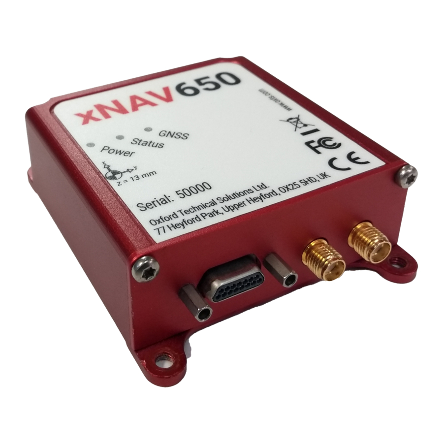
Hz navigation output. Data is automatically logged to the 32 GB eMMC for added data protection. The user must perform visual inspection of equipment before use to ensure there is no damage. Figure 1 and Figure 2 show the key points of note on the xNAV650. The numbered labels are described in Table 3. -
Page 11: Figure 2: Xnav650 Top View
Figure 2: xNAV650 top view Table 3: xNAV650 points of interest Label number Description Main I/O connector (15-way Micro-D) Power Ethernet Serial TX/RX Digital I/O signal 1/2 (configurable) Primary GNSS connector (SMA) Secondary GNSS connector (SMA) Measurement origin point LEDs Oxford Technical Solutions Ltd. -
Page 12: Led Definitions
Description The operating system has not yet booted (this occurs at start-up). Red-green flash The system is asleep. Contact OxTS support for further information. The operating system has booted but the GNSS receiver has not yet output a Red flash valid time, position, or velocity. -
Page 13: Dimensions
Dimensions Figure 3 shows the outer dimensions of the xNAV650, the mounting points, and the measurement origin point. When making measurements required in the configuration files, measurements should be made from the origin point. Figure 3: xNAV650 dimensions and measurement origin point (mm) Oxford Technical Solutions Ltd. -
Page 14: Coordinate Frame
The IMU reference frame shown in Figure 4 is popular with navigation systems – where the positive X- axis points forwards, the positive Y-axis points right and the positive Z-axis points down. The xNAV650 can be mounted in any orientation, it is not necessary for its axes to match those of the host vehicle. -
Page 15: Interfaces
Interfaces Main connector The main I/O connector on the xNAV650 is a 15-way Micro D-sub. Figure 5 shows the pin layout. Figure 5: xNAV650 main connector pin layout Table 7 shows the pin descriptions. Table 7: Main connector pin description... -
Page 16: Pps
Figure 6: PPS waveform Serial The serial interface uses a standard 5V logic RS232. The exact transceiver used is the SN65C3221EPWR. For full details you can read the datasheet from Texas Instruments https://www.ti.com/lit/ds/symlink/sn65c3221e.pdf?ts=1612353780873&ref_url=https%253A%252F%2 52Fwww.ti.com%252Fproduct%252FSN65C3221E Oxford Technical Solutions Ltd. http://www.oxts.com Page 16 of 42... -
Page 17: Digital I/O
Note that triggers are pulled up internally to allow a switch to be used to short them to GND. User cable The standard xNAV650 user cable is designed for quick access to the main interfaces. Figure 7 shows the cable diagram and Table 11 shows the pin descriptions for the interface connectors. At the end of this manual there is a full page drawing of the user cable provided. -
Page 18: Antennas
The xNAV650 is certified for use with GNSS antennae with a gain of less than or equal to 35 dB. When using the xNAV650 in a dual antenna configuration, it is recommended to use the same type of antenna with the same cable lengths for both the primary and secondary receivers. -
Page 19: Ethernet Configuration
The xNAV650 outputs its data over ethernet using a UDP broadcast. The use of a UDP broadcast allows everyone on the network to receive the data sent by the xNAV650. The data rate of the UDP broadcast is 100 Hz. -
Page 20: Best Practices
Best practices Mounting It is essential to mount the xNAV650 rigidly in the vehicle. The xNAV650 should not be able to move or rotate compared to the GNSS antennas, otherwise the performance will be reduced. In most circumstances the xNAV650 should be mounted directly to the chassis of the vehicle. If the vehicle experiences high shocks, then vibration mounts may be required. -
Page 21: Dual Antenna Systems
Dual antenna systems It is often useful to have an understanding of how the xNAV650 uses the measurements from the dual antenna system. This can lead to improvements in the results obtained. A warmup needs to be completed for using the INS but if you have completed one the result of it can be saved and following warmups only need to be around 3 minutes, see the last step for this. -
Page 22: Multipath Effects On Dual Antenna Systems
Figure 9: Dual antenna orientations a) The bases of the antennas are parallel, but the cables exit in different directions. Oxford Technical Solutions Ltd. http://www.oxts.com Page 22 of 42... -
Page 23: Xnav650 Orientation And Alignment
1 m, 5 m and 15 m lengths. This is important because the signal can deteriorate over longer cables and the signals are expected to match. xNAV650 orientation and alignment The orientation of the xNAV in the vehicle is normally specified using three consecutive rotations that rotate the xNAV to the vehicle’s co-ordinate frame. -
Page 24: Specifications
Specifications Specifications for xNAV650 can be found in Tables 11, 12 and 13. These specifications are listed for operation of the system under the following conditions: ▪ After a warm-up period of three minutes’ continuous operation. ▪ Using combined post-processing the highest specification can be achieved effectively instantly for the entire duration of the dataset but the warm-up manoeuvres should always be performed. -
Page 25: Table 13: Xnav650 Physical Characteristics
Gyros Value Full range ±480°/s In-run bias stability 5°/hr Scale factor 0.3% 0.48°/√hr Table 13: xNAV650 physical characteristics Parameter Value Input voltage 5-30 V dc Power consumption Dimensions 77 × 63 × 24 mm Mass 0.13 kg Operating temperature -40 to 70°C Calibration temperature -20 to 70°C... -
Page 26: Notes On Specifications
▪ The heading accuracy that can be achieved by the dual antenna system in the xNAV650 is 0.2° 1σ per metre of separation in ideal, open sky conditions. The system can provide these accuracies in static and dynamic conditions. - Page 27 The accelerometer and gyro sensors used in the xNAV650, as well as the xNAV650 navigation system as a whole, does not fall under the requirements for controlled items on the Commerce Control List (CCL). As such the xNAV650 is designated ECCN 7A994 meaning no licence is required for export or reexport.
-
Page 28: Software Installation
C:\Program Files\OxTS on 32 bit operating systems. The first time some OxTS applications are run, a firewall warning message similar to that shown in Figure 10 may be triggered. This is because the program is attempting to listen for, and communicate with, OxTS devices on the network. -
Page 29: Figure 10: Windows Firewall Warning Message
Figure 10: Windows Firewall warning message Ensure both Private and Public networks are selected to ensure the software can continue functioning when moving from one type to another. Oxford Technical Solutions Ltd. http://www.oxts.com Page 29 of 42... -
Page 30: Operating Principles
Operating principles This section gives some background information on the components in the xNAV650 and how they work together to give the outputs. A short overview of the algorithm is given and some explanation of how the software works. This section is provided as “interesting information” and is not required for normal operation. -
Page 31: Extended Kalman Filter
Position and velocity are compensated directly, but other measurements like accelerometer bias, have no direct measurements. The Kalman filter tunes these so the GNSS measurements and the inertial measurements match each other as closely as possible. Oxford Technical Solutions Ltd. http://www.oxts.com Page 31 of 42... -
Page 32: Use With Survey Hardware
Data logging A Feature Code can be purchased to allow your xNAV650 device to log ethernet traffic directly onto the unit. This allows you to bypass the need to monitor and record your files in real time. Files can be retrieved from the device in the same way as RD files via FTP interfacing. -
Page 33: Pps And Nmea
Please note that data logging does not work for all LiDAR. Data rates from LiDAR devices can be very large which can be overbearing for the CPU of the xNAV650. For Velodyne LiDAR usage, a 16 laser LiDAR will log comfortably onto the xNAV but a 32 laser LiDAR will not log correctly onto the xNAV. -
Page 34: Pps/Triggers
PPS signals can be set to have the active edge in the falling or rising edge in this tab also. Check your device’s manual to determine which is required. NCOM (navigation data) packets can be set to output on triggers in the ethernet tab. Figure 13: The PPS/Triggers tab in NAVconfig. Oxford Technical Solutions Ltd. http://www.oxts.com Page 34 of 42... -
Page 35: Ptp
- January 6th 1980. This is known as the GPS epoch and from this the device can calculate the current date and time. By default, when an OxTS device is used with PTP, it will be using the GPS epoch. -
Page 36: Cable Modification
Finally, ensure that your survey device is correctly configured to anticipate PTP time synchronisation. Cable modification The standard user cable for the xNAV650 is shown in Figure 7. This has been made to be ideal for modification to the user’s selected purpose. Using the cable wiring diagram and the wiring guide shown at the end of this document you will be able to wire up a cable with a suitable connector to interface with whichever requirements you have. -
Page 37: Appendix
I/O Signal 2/Rx 2, 3 I/O Signal 1/Tx 4, 5 W/RED Signal Ground W/BLK Signal Ground (ISO) Serial For xNAV650, no isolation in this product Micro-d pin Colour Signal Male d-type pin CAN+ (ISO)/RS232 CAN- (ISO)/RS232 Tx W/BLK Signal Ground (ISO) Oxford Technical Solutions Ltd. -
Page 38: Drawings
Appendix 2 Drawings Oxford Technical Solutions Ltd. http://www.oxts.com Page 38 of 42... - Page 39 Oxford Technical Solutions Ltd. http://www.oxts.com Page 39 of 42...
-
Page 40: Revision History
Revision history Oxford Technical Solutions Ltd. http://www.oxts.com Page 40 of 42... - Page 41 Revision history Revision Comments 201117 Draft version last updated 210204 Draft version for website release 210311 Final release for product launch Oxford Technical Solutions Ltd. http://www.oxts.com Page 41 of 42...
- Page 42 Oxford Technical Solutions Ltd...
Need help?
Do you have a question about the xNAV650 and is the answer not in the manual?
Questions and answers