
Related Manuals for CMR Electrical WLW

Summary of Contents for CMR Electrical WLW
- Page 1 CMR Electrical Ltd Bolton House Five Chimneys Lane Hadlow Down East Sussex TN22 4DX Tel: 01825 733600 Water Leak Detection Manual...
-
Page 2: Table Of Contents
Contents System Overview Installation Wiring Water Solenoid Valve Water Flow Sensor Optional water detection cable sensor Relay output Home screen explained Setup page explained Sleep Mode explained Holiday Mode explained Help window explained Setting up the system Alarms their meanings and what to do about it... -
Page 3: System Overview
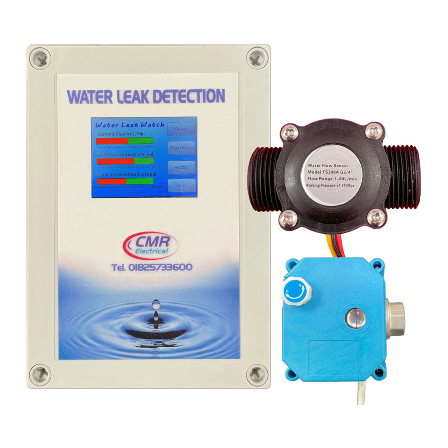
1) System Overview Being fully programmable to suite user requirements, the alarm unit is connected to a flow sensor and water shutoff valve. All three items should be positioned as close as possible to the incoming water supply pipe with the flow sensor and valve fitted just after the internal stopcock. Designed to monitor the flow of water entering the building, flat or area, the unit raises an alarm and shuts of the water supply when the flow exceeds pre-set limits. -
Page 4: Wiring
Input Power Shutoff valve Wiring connections see below Optional water detection cable Wiring connections see below Water flow sensor Wiring connections see below 3) Wiring Detail 230VAC 5A Normally open Mains Supply Contact rated at 250mA 24V Cable Screen Wire Water Flow Sensor 12VDC... -
Page 5: Water Solenoid Valve
4) Water Solenoid Valve The shutoff valve is a ½” or ¾” BSP female/female, Normally Open, power shut, 12VDC, 5W with position indicator and Override switch. To override the valve in an emergency, and allow water to flow with the unit in still in alarm. First pull the override switch toward you until the white knob is just clear of the blue housing. -
Page 6: Optional Water Detection Cable Sensor
6) Optional water detection cable sensor The two water detection cable wires are not polarity conscious and therefore can be fitted to any “Sig” terminal. To connect the cable, first position it around the area to be protected and connect one of the wires to the 4-way terminal block, terminal “SigA”... -
Page 7: Setting Up The System
12) Help screen This has been provided to help you remember how the system operates with a description of each alarm parameter. 13) Setting up the system Older houses were built with a water storage tank in the loft. This meant that mains pressure and water flow rates were not very important because all the mains had to do was fill the tank and provide clean water to kitchen. -
Page 8: Alarms Their Meanings And What To Do About It
Setting up the “Volume Used without a Break” alarm trip point Enter setups and adjust the alarm setpoint as described in “Setting up the Water Flow without a Break alarm trip point” (minimum 100 maximum 2000 litres). This setting is volume based and is dependent upon whether the property uses large quantities of continually flowing water i.e., garden hose used every day. - Page 9 Water Has Been Found This screen will only be activated if you have an external water detection sensor or cable (see section 2) connected to the device and the device has come into contact with water. This is an On or Off alarm with no setting to adjust.
Need help?
Do you have a question about the WLW and is the answer not in the manual?
Questions and answers