Table of Contents
Advertisement
Notes: Please use this manual together with service manual
Model No.[SA-AKX100PSK], Order no. (PSG1608001CE).
• CD Mechanism Unit (BRS12C) , Order No. PSG1303059AE
• Speaker system SB-UX100GN-K, Order No: PSG1609002AE
TABLE OF CONTENTS
1 Notes ----------------------------------------------------------------- 3
2 Safety Precautions----------------------------------------------- 3
2.1. General Guidelines---------------------------------------- 3
2.2. Before Repair and Adjustment ------------------------- 4
2.3. Protection Circuitry ---------------------------------------- 5
2.4. Caution For AC Cord (For E/GS) ---------------------- 6
2.5. Safety Parts Information -------------------------------- 7
3 Specifications ----------------------------------------------------- 8
4 Location of Controls and Components ------------------- 9
4.1. Remote Control Key Button Operation--------------- 9
Model No.
Product Color: (K)...Black Type
PAGE
4.2. Main Unit Key Button Operation---------------------- 10
5 Disassembly and Assembly Instructions--------------- 11
here is the change for this model -------------------- 11
6 Schematic Diagram -------------------------------------------- 13
6.1. Main (MICON) Circuit (1/2) ---------------------------- 13
6.2. Main (MICON) Circuit (2/2) ---------------------------- 14
6.3. Main (AUX Tuner) Circuit ------------------------------ 15
6.4. Main (DAMP) Circuit ------------------------------------ 16
© Panasonic Corporation 2016. All rights reserved.
Unauthorized copying and distribution is a violation of
law.
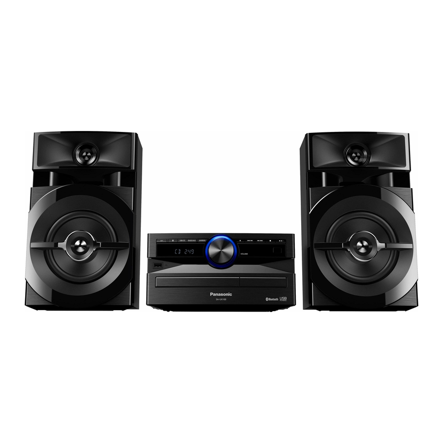
CD Stereo System
SA-UX100E
SA-UX100GN
SA-UX100GS
PSG1609001AE
PAGE
Advertisement
Table of Contents

Related Manuals for Panasonic SA-UX100E


Summary of Contents for Panasonic SA-UX100E
-
Page 1: Table Of Contents
4 Location of Controls and Components ------------------- 9 6.3. Main (AUX Tuner) Circuit ------------------------------ 15 4.1. Remote Control Key Button Operation--------------- 9 6.4. Main (DAMP) Circuit ------------------------------------ 16 © Panasonic Corporation 2016. All rights reserved. Unauthorized copying and distribution is a violation of law. - Page 2 6.5. Main (Voltage Regulator) Circuit --------------------- 17 7 Printed Circuit Board ------------------------------------------ 18 7.1. Main P.C.B. ------------------------------------------------ 18 8 Exploded View and Replacement Parts List ----------- 19 8.1. Cabinet Parts Location 1 ------------------------------- 19 8.2. Packaging -------------------------------------------------- 20 8.3. Mechanical Replacement Part List ------------------ 21 8.4.
-
Page 3: Notes
1 Notes This simplified service manual is base on SA-AKX100PS (Order No. PSG1608001CE). 1) This service manual contains only following information - Safety Precautions - Specifications - Locations of Controls and Components - Disassembly and Assembly Instructions - Location of Rear Shield - Schematic Diagram - Main (MICON) Circuit - Main (Aux Tuner) Circuit... -
Page 4: Before Repair And Adjustment
2.1.2. Leakage Current Hot Check 1. Plug the AC cord directly into the AC outlet. Do not use an isolation transformer for this check. 2. Connect a 1.5kΩ, 10 watts resistor, in parallel with a 0.15μF capacitors, between each exposed metallic part on the set and a good earth ground such as a water pipe, as shown in Figure 1-1. -
Page 5: Protection Circuitry
2.3. Protection Circuitry The protection circuitry may have operated if either of the following conditions are noticed: • No sound is heard when the power is turned on. • Sound stops during a performance. The function of this circuitry is to prevent circuitry damage if, for example, the positive and negative speaker connection wires are “shorted”, or if speaker systems with an impedance less than the indicated rated impedance of the amplifier are used. -
Page 6: Caution For Ac Cord (For E/Gs)
2.4. Caution For AC Cord (For E/GS) Figure 1-3... -
Page 7: Safety Parts Information
2.5. Safety Parts Information Safety Parts List: There are special components used in this equipment which are important for safety. These parts are marked by in the Schematic Diagrams, Exploded View & Replacement Parts List. It is essential that these critical parts should be replaced with manufacturer’s specified parts to prevent shock, fire or other hazards. -
Page 8: Specifications
(approximate) (With “BLUETOOTH STANDBY” set to “ON”) Note: 1. Specifications are subject to change without notice. Mass and dimension are approximate. 2. Total harmonic distortion is measured by the digital spectrum analyzer. System: SC-UX100E-K Main Unit: SA-UX100E-K Speakers: SB-UX100GN-K... -
Page 9: Location Of Controls And Components
4 Location of Controls and Components 4.1. Remote Control Key Button Operation... -
Page 10: Main Unit Key Button Operation
4.2. Main Unit Key Button Operation... -
Page 11: Disassembly And Assembly Instructions
5 Disassembly and Assem- Step 4 Release catches. Step 5 Remove Rear Cabinet. bly Instructions 5.1. With reference to original ser- vice manual Section 8.9 “Dis- assembly of Rear Cabinet”, here is the change for this model • Refer to “Disassembly of Top Cabinet”. •... -
Page 13: Schematic Diagram
DA: MAIN (DAMP): SCHEMATIC DIAGRAM - 5 JK6400 R2422 LB6404 VR: MAIN (VOLTAGE REGULATOR): SCHEMATIC DIAGRAM - 6 J0JHC0000118 IC2501 PW_SYS_3R3V C0DBZYY00716 USB_D- USB SWITCH USB_OVC USB_PCONT USB PORT (PLAY) USB_D+ R6402 C6404 PW_5V 470K VOUT C2506 C2507 LB6401 J0JHC0000118 SA-UX100E/GN/GS MAIN (MICON) CIRCUIT... -
Page 14: Main (Micon) Circuit (2/2)
AU: MAIN (AUX TUNER): SCHEMATIC DIAGRAM - 3 C2143 R2499 DS: MAIN (DSP): SCHEMATIC DIAGRAM - 4 0.22 2.2K BT: MAIN (BLUETOOTH): SCHEMATIC DIAGRAM - 4 DA: MAIN (DAMP): SCHEMATIC DIAGRAM - 5 VR: MAIN (VOLTAGE REGULATOR): SCHEMATIC DIAGRAM - 6 SA-UX100E/GN/GS MAIN (MICON) CIRCUIT... -
Page 15: Main (Aux Tuner) Circuit
MI: MAIN (MICON): SCHEMATIC DIAGRAM - 1 ~ 2 DS: MAIN (DSP): SCHEMATIC DIAGRAM - 4 BT: MAIN (BLUETOOTH): SCHEMATIC DIAGRAM - 4 DA: MAIN (DAMP): SCHEMATIC DIAGRAM - 5 VR: MAIN (VOLTAGE REGULATOR): SCHEMATIC DIAGRAM - 6 SA-UX100E/GN/GS MAIN (AUX TUNER) CIRCUIT... -
Page 16: Main (Damp) Circuit
R6054 SPEAKER PROTECTION C6068 SWITCH 6.8K AU: MAIN (AUX TUNER): SCHEMATIC DIAGRAM - 3 DS: MAIN (DSP): SCHEMATIC DIAGRAM - 4 BT: MAIN (BLUETOOTH): SCHEMATIC DIAGRAM - 4 VR: MAIN (VOLTAGE REGULATOR): SCHEMATIC DIAGRAM - 6 SA-UX100E/GN/GS MAIN (DAMP) CIRCUIT... -
Page 17: Main (Voltage Regulator) Circuit
MI: MAIN (MICON): SCHEMATIC DIAGRAM - 1 ~ 2 16V220 AU: MAIN (AUX TUNER): SCHEMATIC DIAGRAM - 3 DS: MAIN (DSP): SCHEMATIC DIAGRAM - 4 R1018 BT: MAIN (BLUETOOTH): SCHEMATIC DIAGRAM - 4 DA: MAIN (DAMP): SCHEMATIC DIAGRAM - 5 SA-UX100E/GN/GS MAIN (VOLTAGE REGULATOR) CIRCUIT... -
Page 18: Printed Circuit Board
R6011 Q6300 LB2558 R1015 C6500 C6592 C6064 C1045 LB2556 C6068 C6083 R6067 C1023 R2580 Q6001 LB2029 C1026 R6132 Q1000 LB2027 Q6007 R1062 R1060 R6056 L6005 C1033 CN1002 Q6002 R1038 (TO SMPS P.C.B.) C1032 R6076 6289-1 PbF 6289-1 SA-UX100E/GN/GS MAIN P.C.B. -
Page 19: Exploded View And Replacement Parts List
8 Exploded View and Replacement Parts List 8.1. Cabinet Parts Location 1 *(SMPS MODULE) SA-UX100 NOTE: " * " PART IS NOT SUPPLIED / REF IS FOR INDICATION ONLY. CABINET DRAWING... -
Page 20: Packaging
8.2. Packaging ACCESSORIES BAG (FOR E & GS ONLY) (FOR E & GS ONLY) REMOTE CONTROL (FOR GN ONLY) A3 OI BOOK (FOR GS ONLY) FM INDOOR ANTENNA SA-UX100 A5 ANTENNA PLUG ADAPTOR (FOR E ONLY) SB-UX100 F R O N T POLYFOAM (LEFT) POLYFOAM (RIGHT) SC-UX100... -
Page 21: Mechanical Replacement Part List
8.3. Mechanical Replacement Part List Safety Ref. Part No. Part Name & Qty Remarks Description RSC1228A THERMAL PAD Safety Ref. Part No. Part Name & Qty Remarks RMZX1022-1 PCB SPACER Description RKAX0042-K LEG CUSHION CABINET RHD26046-L SCREW CHASSIS XTB3+10JFJ-J SCREW RHD30007-K2J SCREW REE1730... - Page 22 Safety Ref. Part No. Part Name & Qty Remarks Description K2CQ2YY00119 AC CORD E,GS K2CT2YY00097 AC CORD E,GS TQBJ0969 O/I (En) GN,GS TQBJ0970 O/I (Cn) TQBJ0971 (Ge/Fr/It/ TQBJ0972 O/I (Sp/Po/Cz) TQBJ0975 O/I (Ar) TQBJ0976 (En/Sw/Da/ RSAX0002 INDOOR ANTENNA K1YZ02000013 ANTENNA PLUG ADAPTOR...
-
Page 23: Electrical Replacement Part List
8.4. Electrical Replacement Part List Safety Ref. No. Parts No. Parts name & Description Remarks SA-AKX100PS SA-UX100E/GN/GS PCB1 TNPA6289 TNPA6289AC MAIN P.C.B (RTL) E PCB1 TNPA6289AB TNPA6289AD MAIN P.C.B (RTL) GN, GS IC2003 RFKWFKX100LM RFKWFUX100GM (E.S.D) C1033 F1H1H103B047 680 1/10W... - Page 24 Safety Ref. No. Parts No. Parts name & Description Remarks SA-AKX100PS SA-UX100E/GN/GS R2004 D0GBR00J0004 J0JCC0000309 Inductor R2006 D0GBR00J0004 J0JCC0000309 Inductor R2015 D0GAR00J0005 J0JYC0000100 Inductor R2016 D0GAR00J0005 J0JYC0000100 Inductor R2017 D0GAR00J0005 J0JYC0000100 Inductor R2018 D0GAR00J0005 J0JYC0000100 Inductor R2019 D0GAR00J0005 J0JYC0000100 Inductor...
Need help?
Do you have a question about the SA-UX100E and is the answer not in the manual?
Questions and answers