
Related Manuals for Brasch GSE Generation 2


Summary of Contents for Brasch GSE Generation 2
- Page 1 GSE Generation 2 Installation / Operation Manual Brasch Environmental Technologies, LLC 140 Long Road, Suite 101 Chesterfield, Missouri 63005 314-291-0440 www.braschenvtech.com...
-
Page 2: Table Of Contents
Table of Contents Introduction...........................4 General Description........................4 Features and Benefits......................5 Technical Specifications........................6 Product Specifications......................6 Target Gas Specifications......................7 Carbon Monoxide.........................7 Nitrogen Dioxide........................7 Description of Front Panel Indicators..................8 Front Panel Indicators......................8 Operation Safety Notice........................9 Types of Notices........................9 Quick Start Guide........................10 Step 1 – Mounting........................10 Step 2 –... - Page 3 Active Zones........................26 Zone Delay.........................26 Zone Alert...........................26 High Alert Relay Operation....................27 Fan Speed..........................27 Proportional Output......................27 Using the Proportional Outputs....................27 Obtaining the Best Operation....................28 Carbon Monoxide and/or Nitrogen Dioxide Detectors............28 Maintenance..........................30 Testing the Response to the Target Gas................30 Carbon Monoxide and/or Nitrogen Dioxide Detectors............30 Replacing the Sensor......................31 Suggested Repair Parts......................32 Troubleshooting..........................33...
-
Page 4: Introduction
Introduction General Description The Brasch Environmental Technologies GSE Generation 2 Gas Detector is designed to function as a dual-zone standalone gas sensor and ventilation controller. The detector consists of a sensor (or sensors), six control relays, and digital control circuitry. The unit monitors the signal from the sensor, compares the signal to preset values, and controls relay contacts based upon the comparison. -
Page 5: Features And Benefits
Features and Benefits • Comprehensive Monitoring ◦ Detects CO and/or NO • Greater Coverage ◦ Monitors up to 4 Sensors and 36,000 sq. ft. • More Control ◦ User-Adjustable Setpoints, Delays, Outputs, and Relays ◦ Built-in Manual Fan Activation • Enhanced Durability ◦... -
Page 6: Technical Specifications
Technical Specifications Product Specifications Input Power 120 VAC, 50/60 Hz, 0.2 A (selected at time of order) 24 VAC, 50/60 Hz, 1.0 A Installation Category II (local level, over-voltage transients less than 500V) Storage Temperature -50°C to 120°C (-58°F to 248°F) Operating Temperature -20°C to 50°C (-4°F to 122°F) Humidity... -
Page 7: Target Gas Specifications
Brasch Environmental Technologies, LLC has designed their detectors so that the measurement ranges for each target gas meet the agencies’ requirements. Each target gas, for which Brasch currently produces a detector, is listed below along with the relevant concentration specifications. -
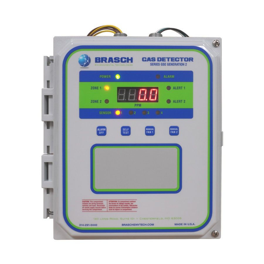
Page 8: Description Of Front Panel Indicators
Description of Front Panel Indicators The front panel indicators convey to the user the operational status of the detector. The following table describes the function of each indicator. Please refer to the detector’s front panel label for the indicator’s location. Front Panel Indicators Indicator Color... -
Page 9: Operation Safety Notice
Operation Safety Notice Certain procedures and operations detailed in this manual require that specific precautions be taken prior to beginning the procedure or operation. When precautions are required, a notice will be printed in an appropriate location in the manual. The user is urged to read and understand all such notices. -
Page 10: Quick Start Guide
Operation with the wrong power requirement will void the manufacturer’s warranty and the installer will be responsible for any damage that occurs. Contact Brasch Environmental Technologies, LLC before connecting power to the detector if you are unsure of the correct power requirement. IOM01... -
Page 11: Step 3 - Remote Transmitter Wiring
CAUTION It is very important that the power and signal connections between each transmitter and between the transmitters and the Brasch controller be correct. If the connections are wired incorrectly, damage to both the transmitters and the controller will occur. -
Page 12: Step 4 - Relay Wiring
Step 4 – Relay Wiring In most cases, wiring of the ventilation control relays can be completed without opening the front panel of the detector. Color-coded wires connected to the internal relay terminals extend outside the housing through the conduit connector located at the top, left of the unit. Use only the necessary wires required for control of the ventilation components. -
Page 13: Step 7 - Self-Test Mode
Step 7 – Self-Test Mode This detector is equipped with a self-test mode that can be activated any time after warm-up by pressing the “SELF TEST” button for approximately 1 second. This mode will test the display, indicator LEDs, relays, and buzzer for proper operation. Any ventilation components connected to these relay terminals will operate if their power supply is active. -
Page 14: Installation
Installation Mounting the Detector The ability of the detector to sense the target gas and efficiently control the ventilation system depends greatly upon proper selection of the mounting location. This detector monitors the area around it by sampling the air that passes by the sensor. Since the sensor is mounted inside a housing, air must diffuse through the intake vents and pass by the sensor on its way out the exhaust vents. -
Page 15: Connecting The Power Supply
Only qualified personnel should attempt to install, maintain, or service this equipment. Brasch Gas Detectors are designed to operate from either 120 VAC or 24 VAC. Selection of the operating voltage is made by the user at the time the detector is ordered. The correct voltage is listed on the label in the lower, left corner of the front panel. - Page 16 Contact Brasch Environmental Technologies, LLC before connecting power to the detector if you are unsure of the correct power requirement. Color-coded wires exiting the detector housing through the top, right conduit connector are provided for connecting the operating voltage to the detector.
-
Page 17: Connecting The Remote Transmitters
44 to determine the proper connections at the controller. Connecting the Ventilation System As an energy saving device, the main function of the Brasch Gas Detector is to operate the ventilation system only when necessary. To accomplish this, the detector is equipped with three control relays per zone with color-coded wires exiting the detector housing through the top, left conduit connector. -
Page 18: Connecting The External Alarm
Figures 2, 3, 4, and 5 on pages 21 and 22 show typical alarm wiring. Connecting the Voltage or Current Proportional Output The Brasch GSE Generation 2 Gas Detectors include circuits that provide either a current loop or voltage proportional output for each gas sensor. Each output produces a linear response over the full scale range of the sensor. -
Page 19: Using The Self-Test Feature
Using the Self-Test Feature The self-test feature on this detector provides a convenient way to test the major functions of the complete system. This feature can only be activated after the unit has completed its warm- up phase. Activate the self-test by pressing the “SELF TEST” button for approximately one second. -
Page 20: Typical Installation Diagrams
Typical Installation Diagrams Figure 1: Wiring – Typical Layout IOM01 Rev 1.0 – December 22, 2020... - Page 21 Figure 2: Wiring - Single Fan Ventilation System with One Zone Figure 3: Wiring - Single Fan Ventilation System with Two Zones IOM01 Rev 1.0 – December 22, 2020...
- Page 22 Figure 4: Wiring - Two Fan Ventilation System with One Zone Figure 5: Wiring - Two Fan Ventilation System with Two Zones IOM01 Rev 1.0 – December 22, 2020...
-
Page 23: Operation
Operation How the Detector Senses the Target Gas Ambient air surrounding the detector housing diffuses inside the housing where it comes into contact with the sensor. Although the detector’s circuitry dissipates very little power, a small amount of heat is produced inside the housing. This heat causes air to rise up through the bottom vents, past the sensor(s), and out the upper vents on either side of the unit. -
Page 24: Alarm
target gas concentration rise quicker than the Low Alert delay time, the High Alert condition will be activated immediately, regardless of how much time is left in the delay period. If the unit is set for “50/100” operation, both the Low Alert and High Alert relays will close simultaneously. The High Alert relay will remain closed until the target gas concentration drops below the Low Alert threshold. -
Page 25: Factory Default Settings
Factory Default Settings Unless otherwise specified on the order form, the following settings will be used to configure the detector. Setting Default Sensor 1 Active Sensor 2 Active if Applicable Sensor 3 Active if Applicable Sensor 4 Active if Applicable Zone 1 Active Zone 1 Delay... -
Page 26: Adjusting The Settings
Adjusting the Settings Note Power to the detector must be turned off in order for any changes made to take effect. Sensor Number The sensor number is set by SW1 on the right side of each sensor board using a binary counting system. -
Page 27: High Alert Relay Operation
Using the Proportional Outputs This Brasch Gas Detector is supplied with a linear proportional output for each sensor that can be connected to a building management controller or variable-frequency drive. These outputs can produce either a current or voltage signal that is proportional to the concentration of the target gas present at the sensor. -
Page 28: Obtaining The Best Operation
14 on page 45 of this manual. As an example, a Brasch Carbon Monoxide Detector has a full scale output of 200 PPM CO. For the 4-20 mA output mode, 0 PPM CO would equal 4 mA while 200 PPM CO would equal 20 mA. - Page 29 delay period occurs between the time the Low Alert level is exceeded and the fans activate, and between the time the target gas concentration drops below the Low Alert level and the fans turn off. While the delay is in progress, the appropriate alert indicator will blink short-on- long-off as the time proceeds toward zero.
-
Page 30: Maintenance
Maintenance Testing the Response to the Target Gas Carbon Monoxide and/or Nitrogen Dioxide Detectors Testing these detectors requires that the target gas be applied to the sensor using one of two methods. Gas can be applied from a tank of air containing a known concentration of the target gas or from the exhaust of an operating engine to produce a level of target gas sufficient to activate the detector. -
Page 31: Replacing The Sensor
However, sufficient response can be obtained to determine that the detector is working. Brasch Environmental Technologies recommends testing the detector once every six months to ensure proper response and accuracy. Replacing the Sensor The sensor’s useful lifetime depends greatly upon its operating conditions. -
Page 32: Suggested Repair Parts
Fuse, TR5, time-lag, 0.250 A, 250 VAC Sensor Board Negative Fuse TR5-0.250 Fuse, TR5, time-lag, 1.0 A, 250 VAC Sensor Board Positive Fuse TR5-1.0 A package containing the proper quantities of fuses can be purchased through your Brasch distributor. IOM01 Rev 1.0 – December 22, 2020... -
Page 33: Troubleshooting
Troubleshooting Error Codes The Brasch GSE Generation 2 Gas Detector is programmed to display error codes to indicate a problem condition with the unit. Code Description 9501 Transmit Timeout 9601 Failed Communication with Sensor 1 9602 Failed Communication with Sensor 2... -
Page 34: Cannot Run Self-Test - 9802
The most common reason for this error code is improper wiring between the sensor board and control board. Another reason is that the sensor is numbered incorrectly, either matching the designation of another sensor or being set to a number set as inactive on the control board. Cannot Run Self-Test –... -
Page 35: No Active Zones - 9998
No Active Zones – 9998 This error will only appear if there is damage to the zone assignment circuit. It is not possible to achieve this error under normal operating conditions. Replace the control board to correct the error. No Active Sensors – 9999 If all sensors are set as inactive at SW3 on the control board, this error code will appear. -
Page 36: Common Installation/Operation Mistakes
Common Installation/Operation Mistakes Ventilation Components Connected to the Wrong Relays A common mistake is to control a single fan ventilation system using the “A2 COM” and “A2 NO” relay contacts. If connected this way, the fan will not activate until the target gas concentration exceeds High Alert level. -
Page 37: Delay Period Set Incorrectly
produces the best overall operation. Be sure to check all applicable federal, state, and local guidelines as these may dictate the required concentration. Delay Period Set Incorrectly Using a long delay period can produce a situation in which a rapidly increasing gas level may rise to dangerous concentrations before the ventilation system activates. -
Page 38: Limited Warranty
If service or repair of your Brasch product becomes necessary, an authorization request for returning the product to the Brasch factory must be obtained from our sales office. If you are an end user, please contact your Brasch distributor to initiate this request. The distributor, after obtaining a description of the problem, will contact the factory and request a Return Goods Tag (RGT) number. -
Page 39: Appendix
Appendix Model Numbers and Descriptions Each Brasch Gas Detector is given a model number that describes the type(s) of target gas(es) and the operating voltage. This model number appears on the front-panel label. Use the following list to completely identify a detector once you know the model number. -
Page 40: Complete Model Number List
Complete Model Number List Standalone Detector with Local Sensors Voltage CO/NO Remotes Only 24 VAC GSE2-CM-24 GSE2-ND-24 GSE2-NCM-24 GSE2-24 120 VAC GSE2-CM-120 GSE2-ND-120 GSE2-NCM-120 GSE2-120 Remote Sensors Voltage (Supplied by Detector) CO/NO 24 VAC GSE2-CM-Remote GSE2-ND-Remote GSE2-NCM-Remote Note The detector is only capable of handling up to four sensors in any combination of local and remote mounting placement. -
Page 41: Figures And Diagrams
Figures and Diagrams Figure 6: Front Cover Layout IOM01 Rev 1.0 – December 22, 2020... - Page 42 A1 COM A1 NC Blue A2 NO A2 COM Blue A2 NC Purple ALR COM Purple ALR NC Zone 2 (TS3) Yellow A1 COM Yellow A1 NC Brown A2 NO Brown A2 COM A2 NC Gray ALR COM Gray ALR NC Zone 1 (TS2) Figure 7: Relay Wiring Color Code EARTH...
- Page 43 50/100 Configuration (Factory Default) 2-SPEED Configuration Figure 9: Fan Settings Brown Blue Black Green Figure 10: Sensor Wiring Color Code – Control Board IOM01 Rev 1.0 – December 22, 2020...
- Page 44 +UNREG Green Black -UNREG Blue -COMM +COMM Brown Figure 11: Sensor Wiring Color Code – Sensor Board Sensor 1 Sensor 2 Sensor 3 Sensor 4 Figure 12: Sensor Assignment IOM01 Rev 1.0 – December 22, 2020...
- Page 45 4-20 mA JP2 JP3 2-10 VDC JP2 JP3 1-5 VDC JP2 JP3 0.2-1 VDC JP2 JP3 Figure 13: Proportional Output Settings Carbon Monoxide Output (mA) Nitrogen Dioxide Output (mA) Figure 14: Proportional Output Graphs IOM01 Rev 1.0 – December 22, 2020...
- Page 46 Figure 15: Mounting Dimensions (Not to Scale) IOM01 Rev 1.0 – December 22, 2020...
- Page 47 Figure 16: Detector Assembly – Inside View IOM01 Rev 1.0 – December 22, 2020...
- Page 48 Figure 17: Detector Assembly - Exploded View IOM01 Rev 1.0 – December 22, 2020...
- Page 49 The above figures are not complete lists of all possible desensitizing or contaminating gases or substances. Take caution to evaluate the probable effect of a contaminant not included in the above list. Contact Brasch Environmental Technologies technical support to learn more. IOM01...
- Page 50 Website: www.braschenvtech.com Technical Support Contact Information Phone: 314-291-0440 ext. 1006 Fax: 314-291-0646 Email: customerservice@braschenvtech.com Website: www.braschenvtech.com/support-for-existing-systems Revision: 1.0 Issue Date: December 22, 2020 Document Number: IOM01 © Brasch Environmental Technologies, LLC All Rights Reserved IOM01 Rev 1.0 – December 22, 2020...
Need help?
Do you have a question about the GSE Generation 2 and is the answer not in the manual?
Questions and answers