Table of Contents

Related Manuals for Maretron NBE100

Summary of Contents for Maretron NBE100
- Page 1 _______________________________________________________ NBE100 Network Bus Extender User’s Manual Revision 1.2 Copyright ©2021 Carling Technologies, Inc. 60 Johnson Ave. Plainville, CT 06062 USA All Rights Reserved http://www.maretron.com...
-
Page 2: Table Of Contents
Figure 4 - NBE100 General Tab ....................6 Figure 5 - NBE100 Advanced Tab ..................... 7 Figure 6 - NBE100 PGN Filter Tab .................... 8 Figure 7 - NBE100 Installation Description Tab ................. 9 Figure 8 – Mounting Surface Template ................... 13... -
Page 3: Introduction
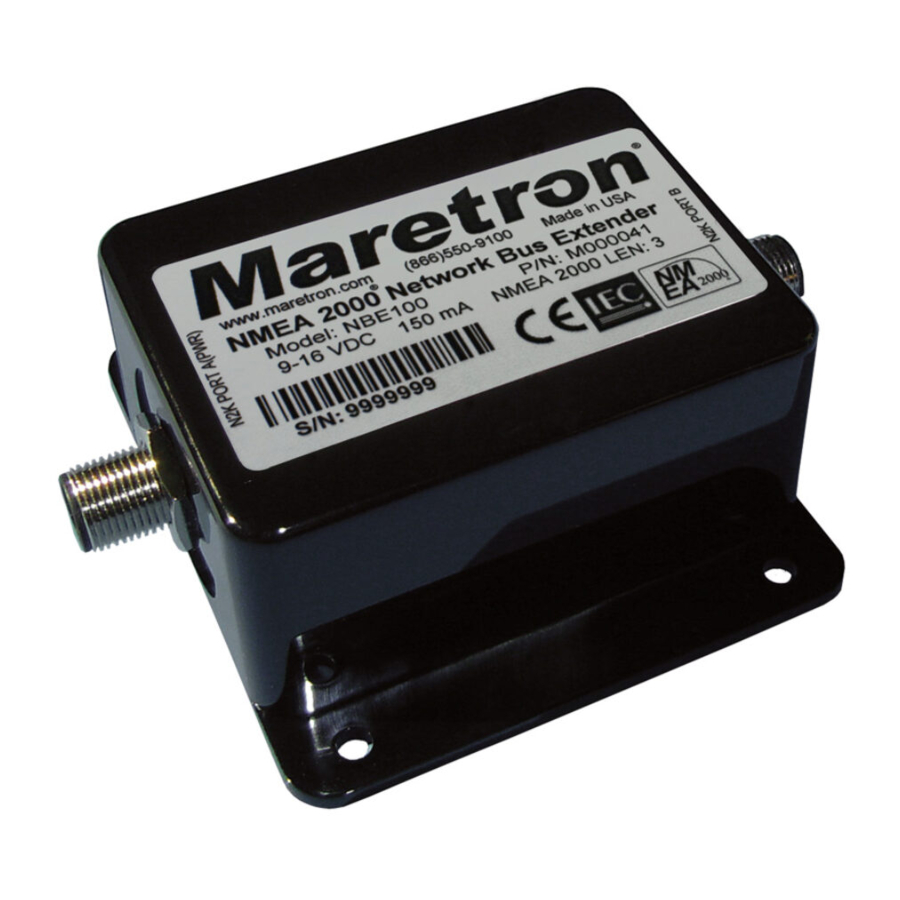
1 Introduction Congratulations on your purchase of the Maretron Network Bus Extender. Maretron has designed and built your NBE100 to the highest standards for years of dependable and accurate service. Maretron's NBE100 (Network Bus Extender) allows you to extend the maximum node count, ®... -
Page 4: Nbe100 Application
_______________________________________________________ 1.3 NBE100 Application The NBE100 can be applied, not only anytime a NMEA 2000® bus needs extending, but also can be used to make only specific communication messaging to be passed between NMEA2000® busses possible. Apply the PGN (Parameter Group Number) Pass Filter and the NBE100 will allow only the desired PGN messages to be passed between the connected NMEA2000®... -
Page 5: Choosing A Mounting Location
(see Figure 2). You connect the ® ® NBE100 to an NMEA 2000 network using a Maretron NMEA 2000 cable (or compatible cable) by connecting the female end of the cable to the NBE100 (note the key on the male connector NBE100 User’s Manual Rev.1.2... -
Page 6: Figure 2 - Nmea 2000 ® Connector Face Views
NBE100 have separate power sources and two termination resistors. This means that if you use an NBE100 to split an existing network into two separate networks, you must provide one additional power connection and two additional termination resistors (one for each side of the NBE100). -
Page 7: Checking Connections
NMEA 2000 display to observe a sensor on the opposite side of the NBE100. If you don’t see data from that sensor, refer to Section 4, “Troubleshooting”. 2.5 Configuring the NBE100 The NBE100 will function on the NMEA 2000 network as it is shipped from the factory;... -
Page 8: Advanced Tab
NBE100 so that each NBE100 is associated with a unique device instance number. The default instance number is 0, which is used to indicate the first NBE100 that is hooked to the network. Subsequent NBE100’s connected to the network would be numbered 1, 2, and so on. -
Page 9: Pgn Filter Tab
2000 network on one port of the NBE100 to the NMEA 2000 network on the other port. If the PGN Filter is enabled the NBE100 will filter all PGNs except for the PGNs entered into the “Exception Field”. Where “CAN1” refers to the NBE100’s “N2K Port A” and “CAN2” refers to the NBE100’s “N2K Port B”, the PGN Filter can filter PGNs traveling from CAN1 to CAN2, CAN2 to... -
Page 10: Installation Description Tab
Figure 6 - NBE100 PGN Filter Tab 2.5.4 Installation Description Tab In the “Installation Description Tab” you can store data to the NBE100 for information about the installation or any notes required. See preceding figure of the NBE100 Installation Description Tab to see it’s content. -
Page 11: Maintenance
• Clean the unit with a soft cloth. Do not use chemical cleaners as they may remove paint or markings or may corrode the NBE100 enclosure or seals. Do not use any cleaners containing acetone, as they will deteriorate the plastic enclosure. -
Page 12: Troubleshooting
_______________________________________________________ 4 Troubleshooting If you notice unexpected operation of the Maretron NBE100, follow the troubleshooting procedures in this section to remedy simple problems. If these steps do not solve your problem, please contact Maretron Technical Support (refer to Section 6 for contact information). -
Page 13: Technical Specifications
NBE100 User's Manual_____________________________________ 5 Technical Specifications As Maretron is constantly improving its products, all specifications are subject to change without notice. Maretron products are designed to be accurate and reliable; however, they should be used only as aids to navigation and not as a replacement for traditional navigation aids and techniques. -
Page 14: Technical Support
_______________________________________________________ 6 Technical Support If you require technical support for Maretron products, you can reach us in any of the following ways: Telephone: 1-866-550-9100 Fax: 1-602-861-1777 E-mail: support@maretron.com World Wide Web: http://www.maretron.com Mail: Carling Technologies, Inc. Attn: Maretron Technical Support 120 Intracoastal Pointe Dr. -
Page 15: Installation Template
NBE100 User's Manual_____________________________________ 7 Installation Template Please check the dimensions before using the following diagram as a template for drilling the mounting holes because the printing process may have distorted the dimensions. Figure 8 – Mounting Surface Template NBE100 User’s Manual Rev.1.2... -
Page 16: Maretron (2 Year) Limited Warranty
Warranty Return Procedure: To apply for warranty claims, contact Carling Technologies or one of its Maretron dealers to describe the problem and determine the appropriate course of action. If a return is necessary, place the product in its original packaging...
Need help?
Do you have a question about the NBE100 and is the answer not in the manual?
Questions and answers