Table of Contents

Related Manuals for Atlas Copco CC 1700 U


Summary of Contents for Atlas Copco CC 1700 U
- Page 1 1700 U, 1700 S Safety and operating instructions Hydraulic demolition cutter Valid from serial number CC 1700 U DEQ139285 CC 1700 S DEQ139285 © 2015 Construction Tools GmbH | No. 3390 5141 01 | 2015-11-16 Original instructions...
-
Page 3: Table Of Contents
CC 1700 U, 1700 S Contents Contents INTRODUCTION..............7 About these Safety and Operating Instructions. - Page 4 Contents CC 1700 U, 1700 S OPERATION............... 35 Preparations before starting.
- Page 5 CC 1700 U, 1700 S Contents Bolt connections/Tightening torques..........52 TROUBLESHOOTING.
-
Page 7: Introduction
The hydraulic demolition cutter CC 1700 with universal jaws is abbreviated in these Instructions to CC 1700 U, hydraulic demolition cutter CC 1700 with steel-cutting jaws to CC 1700 S. The different designation of the texts means as follows: Action step in a safety instruction ►... - Page 8 INTRODUCTION CC 1700 U, 1700 S Symbols used in illustrations have the following meanings: permitted operation prohibited operation © 2015 Construction Tools GmbH | No. 3390 5141 01 | 2015-11-16 Original instructions...
-
Page 9: Safety Instructions
CC 1700 U, 1700 S SAFETY INSTRUCTIONS SAFETY INSTRUCTIONS Signal words This is the safety alert symbol. It is used to alert you to potential personal injury hazards. Obey all safety messages that follow this symbol to avoid possible injury The signal words Danger, Warning, Caution, and or death. -
Page 10: Qualification
SAFETY INSTRUCTIONS CC 1700 U, 1700 S Qualification Intended use Transporting the hydraulic attachment is only Only attach the hydraulic demolition cutter to a permitted if carried out by people who: hydraulic carrier of a suitable load-bearing capacity. Read the carrier manufacturer's Safety and Operating are authorised to operate a crane or a forklift truck ●... -
Page 11: Protective Equipment
CC 1700 U, 1700 S SAFETY INSTRUCTIONS to hit or chop ● Transport, precautions This destroys the hydraulic demolition cutter. ● as a crow bar WARNING Risk of death due to suspended This destroys the hydraulic demolition cutter. loads to push debris ●... -
Page 12: Media/Consumables, Precautions
SAFETY INSTRUCTIONS CC 1700 U, 1700 S If any significant changes are made to the ► WARNING Skin infections/diseases due to hydraulic installation, a new acceptance inspection oil and grease is to be carried out in accordance with the relevant Hydraulic oil and grease can cause rashes (or even national safety provisions. -
Page 13: Electric Shock, Precautions
CC 1700 U, 1700 S SAFETY INSTRUCTIONS Electric shock, precautions Handling machines, precautions DANGER Electrical shock Any contact of the hydraulic attachment with electric WARNING Narcotics, alcohol and drugs circuits or other sources of electricity will lead to an Narcotics, alcohol and medicinal drugs make their electric shock, resulting in serious injury or death. - Page 14 SAFETY INSTRUCTIONS CC 1700 U, 1700 S Dispose of all contaminated material in accordance ► with the applicable environmental regulations. © 2015 Construction Tools GmbH | No. 3390 5141 01 | 2015-11-16 Original instructions...
-
Page 15: Overview
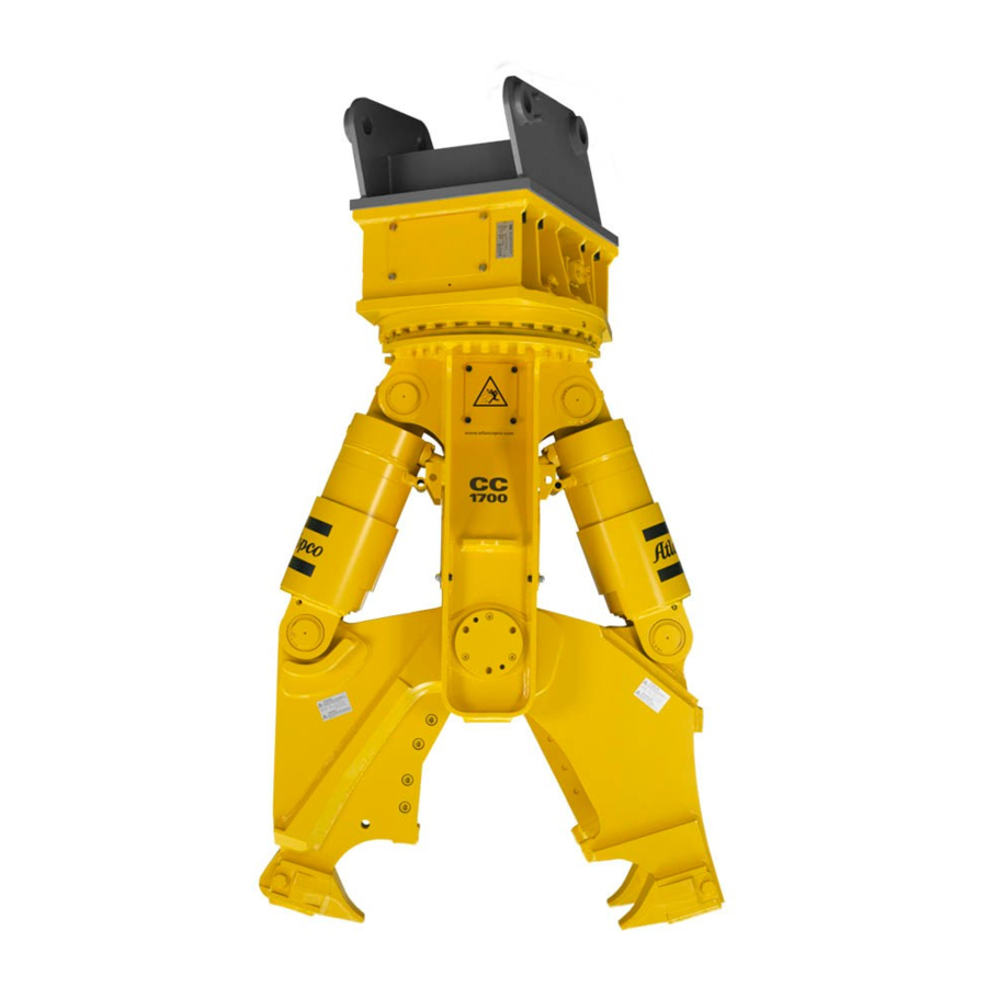
CC 1700 U, 1700 S OVERVIEW CC 1700 S OVERVIEW Equipment description The illustration gives an overview of the main parts and components of the hydraulic attachment. Actual details may differ. CC 1700 U Cutter blades Cutter jaw (double) Four-point bearing Connection function »Turn«... -
Page 16: Function
OVERVIEW CC 1700 U, 1700 S Name plate Function The operation of a hydraulic demolition cutter is described in a simplified version below: Closing the hydraulic demolition cutter The carrier driver operates the cutter valve, via a switch on the floor or via a joystick in the carrier, for the function »Close«. -
Page 17: Labels
CC 1700 U, 1700 S OVERVIEW Labels Applications CC 1700 U and CC 1700 S U version (universal) Field Type of application Demolition work Light to medium-duty building demolition, heavy-duty industrial demolition (heavily reinforced concrete) Cutting profiled steel (general construction steels) -
Page 18: Removing The Packaging
♦ Check that the delivery is complete. ♦ Check the delivery for visual damage. ♦ If any defects are found, consult the Atlas Copco Customer Center/dealer in your area. Scope of delivery The hydraulic demolition cutter is delivered complete with: Hydraulic demolition cutter ●... -
Page 19: Transport
CC 1700 U, 1700 S TRANSPORT TRANSPORT WARNING Hydraulic attachment falling The lifting eye may fail and cause the hydraulic attachment to fall. This may cause serious injury and WARNING Hoist tipping over / hydraulic material damage. attachment falling Check the lifting eye before you lift the hydraulic ►... -
Page 20: Transport Using A Crane
TRANSPORT CC 1700 U, 1700 S Transport the hydraulic demolition cutter with the ♦ Transport using a forklift truck cutter jaws open. There is less oil in the hydraulic demolition cutter if WARNING Hydraulic attachment tipping over the hydraulic demolition cutter is transported with The hydraulic attachment tipping off the fork of the open cutter jaws. -
Page 21: Transport Using A Truck
CC 1700 U, 1700 S TRANSPORT Transport using a truck WARNING Hydraulic attachment tipping over / slipping The hydraulic attachment slipping or tipping over and falling from the loading area of a lorry may cause serious injury. Place the hydraulic attachment on a pallet. -
Page 22: Installation
► Collect any hydraulic oil which escapes. Our hydraulic attachments are basically designed for use with mineral oils. Consult the Atlas Copco ► Dispose of it in accordance with the applicable Customer Center/Dealer in your area before using environmental regulations. -
Page 23: Manufacturing The Adapter Plate
CC 1700 U, 1700 S INSTALLATION Manufacturing the adapter WARNING Hands and fingers being cut off or hurt plate Bores and surfaces can act like a pair of scissors and cut off or hurt parts of your body. Construction Tools GmbH also supplies base plates Never use your fingers to check bores or fitting ►... - Page 24 INSTALLATION CC 1700 U, 1700 S Let your assistant instruct you until the bores in ♦ WARNING Injury by impacts the adapter plate (B) and in the stick (A) are A sudden movement of the carrier may cause your properly aligned.
-
Page 25: Making The Hydraulic Connections
CC 1700 U, 1700 S INSTALLATION Fix the flange halves on both sides of the flange Making the hydraulic connections ♦ with the fixing screws. NOTICE Faulty hydraulic installation The carrier must have a suitable hydraulic installation Position other hose flange for connection »B«. -
Page 26: Removing The Hydraulic Attachment From The Carrier
INSTALLATION CC 1700 U, 1700 S Remove the cap nuts and plugs from the »Turn« ♦ Dismantling the hydraulic connections connections and save them for future use. WARNING Unexpected movement Sudden movements of the carrier may cause serious Check that the connections on the hydraulic ♦... -
Page 27: Removing The Adapter Plate
Assembly rack to hold the cutter jaw pair. Consult relief valve and two throttle valves. The pressure the Atlas Copco Customer Center/Dealer in your relief valve is for the »Turn« function is fixed at 170 area if you want to change the cutter jaw pair. - Page 28 INSTALLATION CC 1700 U, 1700 S Ensure that the hydraulic demolition cutter is Remove the spacer rings (E) ♦ ♦ mechanically and hydraulically attached to the carrier. Ensure that the cutter jaws are connected by two ♦ half rings on each cutter jaw pair.
- Page 29 CC 1700 U, 1700 S INSTALLATION Place the hydraulic demolition cutter with the broad Tighten all Allen screws with the tightening torque ♦ ♦ back of the cutter jaw (double) on the assembly required (see chapter Bolted rack so that the pin lies in the semi-shell of the connections/Tightening torques).
- Page 30 INSTALLATION CC 1700 U, 1700 S Screw the two Allen screws (L) into the cover. Attach the bolt cage (N). ♦ ♦ Unscrew the cover using a rod or pipe. ♦ Drive the main bearing pin (O) out with a copper ♦...
- Page 31 CC 1700 U, 1700 S INSTALLATION The removed cutter jaw pair (Q) remains secured on Let an assistant guide you. ♦ the assembly rack. Move the cutter casing (P) so that the drilled holes ♦ in the cutter casing are flush with those of the cutter jaw pair (Q).
- Page 32 INSTALLATION CC 1700 U, 1700 S Disassemble the bolt cage (N). Secure the cover by fitting the Allen screws (K). ♦ ♦ Tighten the Allen screws (K) with the tightening ♦ torque required (see chapter Bolt connections/Tightening torques). Screw the cover onto the main bearing pin.
- Page 33 CC 1700 U, 1700 S INSTALLATION Loosen all Allen screws (I) at the holders (G) of Pull the bolts (F) out of the cylinder pin bearing of ♦ ♦ the assembly rack. the cutter jaw (double). Disassemble the Allen screws (H,J) from the pin Fit the bolts (F) in the assembly rack semi-shell ♦...
- Page 34 INSTALLATION CC 1700 U, 1700 S Tighten all Allen screws (S) to the tightening torque ♦ required (see chapter Bolted connections/Tightening torques). Remove the spring retainer pins (B) from the lock ♦ pins (A). Remove the lock pins (A) which fix the hydraulic ♦...
-
Page 35: Operation
CC 1700 U, 1700 S OPERATION OPERATION Preparations before starting WARNING Hot hydraulic oil squirting out WARNING Falling carrier The hydraulic system is under high pressure. If A carrier falling or tipping over due to the surface not hydraulic connections come loose, hydraulic oil will being level may cause serious injury and material squirt out under high pressure. -
Page 36: Switching The Hydraulic Demolition Cutter On And Off
Then cut the reinforcements with the cutter blades. ♦ electrical and hydraulic signals.If you have any questions about electric/hydraulic commands, consult the carrier manufacturer and/or the Atlas Copco Customer Center/Dealer in your area. ♦ Switch the hydraulic attachment on and off, as described in the carrier's operating instructions. -
Page 37: Nipping Out Concrete Elements
CC 1700 U, 1700 S OPERATION Nipping out concrete elements Cutting profiled construction steel, pipe ♦ Nip concrete elements off at both sides. ♦ Position the hydraulic demolition cutter so that the blades encompass the profiled construction steel or pipe. -
Page 38: High Ambient Temperature
OPERATION CC 1700 U, 1700 S High ambient temperature Prohibited operation ♦ Only use hydraulic oils of sufficient viscosity. In summer and in tropical climates, the minimum Unsafe base requirement is a hydraulic oil of type HLP 68. WARNING Danger of tipping... -
Page 39: Cutting Rails
CC 1700 U, 1700 S OPERATION Cutting rails Use over the chain WARNING Flying rail fragments WARNING Danger of tipping Rails which break during the cutting process may be The carrier can topple over and cause injuries and flung away and can cause serious injury if people damage. -
Page 40: Moving The Carrier
OPERATION CC 1700 U, 1700 S Moving the carrier Turning the hydraulic attachment ♦ Never relocate the carrier sideways by placing the ♦ Never turn the hydraulic attachment during hydraulic attachment on the ground to lift the breaking/cutting. carrier. This would seriously damage the hydraulic This would seriously damage the hydraulic attachment. -
Page 41: Pulling
CC 1700 U, 1700 S OPERATION Pulling Impacting/chopping ♦ Never pull at girders, supports or walls with the ♦ Do not use the hydraulic attachment to impact or hydraulic attachment. chop to destroy material. This would damage the hydraulic attachment and This would seriously damage the hydraulic the adapter plate. -
Page 42: Cylinder End Positions
OPERATION CC 1700 U, 1700 S Cylinder end positions Cutting high-grade steels ♦ Reposition the carrier to avoid working with the ♦ Only cut profiled steel with a tensile strength < 370 cylinder in its end positions. N/mm Avoid operating the hydraulic attachment when the ♦... -
Page 43: Maintenance
CC 1700 U, 1700 S MAINTENANCE MAINTENANCE WARNING Unexpected movement Sudden movements of the carrier may cause serious injury. The maintenance activities are carried out by the carrier driver. Secure the carrier so that it cannot move ► unexpectedly. WARNING Hot hydraulic oil squirting out The hydraulic system is under high pressure. -
Page 44: Maintenance Schedule
MAINTENANCE CC 1700 U, 1700 S Maintenance schedule prior to shift Check the hydraulic demolition cutter and adapter plate for cracks. Check hydraulic lines for leaks and damage. Check the pipe clamp receiver on the carrier. Check cutter jaws, cutter blade and tips of tooth for wear; if necessary have cutter jaws refaced, turn or replace cutter blades, replace tips of tooth. -
Page 45: Depressurising The Hydraulic System
CC 1700 U, 1700 S MAINTENANCE 10. When you have made sure that no more pressure Depressurising the hydraulic is present in the hydraulic system, you must system disconnect the hydraulic connection to the carrier. Close the shut-off valves or disconnect the... -
Page 46: Lubricating The Four Point Bearing
MAINTENANCE CC 1700 U, 1700 S Inject 4 to 6 strokes of cutter grease per lubrication ♦ Lubricating the four point bearing nipple. Lubrication interval: once a month. ♦ Place the hydraulic demolition cutter vertically on the cutter jaws. ♦... -
Page 47: Checking Hydraulic Lines
CC 1700 U, 1700 S MAINTENANCE Secure the carrier such that it cannot move ♦ Checking the adapter plate unexpectedly. bolts for wear Prior to starting work, check cutter jaws, cutter ♦ blade and tips of tooth for wear. ♦... -
Page 48: Checking The Blade Seat
MAINTENANCE CC 1700 U, 1700 S Perform work while outside the open cutter jaws, ♦ Checking the blade seat not between them. The blade seat should not have any severe damage since this means the support of the cutter blade (B) Disconnect the hydraulic supply to the hydraulic ♦... -
Page 49: Changing The Tip Of The Tooth
CC 1700 U, 1700 S MAINTENANCE Hammer the tip of the tooth (B) out of the guide ♦ Changing the tip of the tooth (C). Removing the tip of the tooth Open the cutter jaws completely. ♦ ♦ Place the hydraulic demolition cutter horizontal on the ground. -
Page 50: Checking And Correcting The Blade Clearance
MAINTENANCE CC 1700 U, 1700 S Open the shut-off valves of the lines »Open ♦ Correcting the blade clearance hydraulic demolition cutter« (Connection »A«) Shims are required to correct the blade clearance. and »Close hydraulic demolition cutter« These are not included in the hydraulic demolition (Connection »B«) at the boom. - Page 51 CC 1700 U, 1700 S MAINTENANCE WARNING Metal chips shooting off The cutter blades are made of hardened steel. When removing the cutter blades with a hammer, chips may shoot off and cause serious eye injuries. Wear safety glasses when hammering out the ►...
-
Page 52: Bolt Connections/Tightening Torques
MAINTENANCE CC 1700 U, 1700 S Bolt connections/Tightening torques The bolt connections of hydraulic demolition cutters are subjected to very high loads. Tighten any loose connections without exceeding the recommended tightening torques. ♦ Connection point Pos. Interval Type of spanner / size... -
Page 53: Troubleshooting
CC 1700 U, 1700 S TROUBLESHOOTING TROUBLESHOOTING Hydraulic demolition cutter does not work Cause Remedy Shut-off valve in line A and/or B closed Check and open shut-off valve Carrier driver Defective couplings blocking lines A and B Check coupling halves and replace defective coupling halves... -
Page 54: Oil Leaks From Hydraulic Ports
TROUBLESHOOTING CC 1700 U, 1700 S Oil leaks from hydraulic ports Cause Remedy Flange halves and/or cap nuts are loose Check and tighten flange halves and/or cap nuts (see Carrier driver chapter Bolt connections/Tightening torques) Oil leak at parts of the hydraulic demolition cutter installation (bolted connections, hoses etc.) -
Page 55: Repair
♦ For technical support contact the Atlas Copco Customer Center/Dealer in your area. WARNING Hot parts The hydraulic cylinder, hoses, pipes and fittings become very hot during operation. Touching them Sending in the hydraulic may lead to burns. - Page 56 REPAIR CC 1700 U, 1700 S Welding hard facing of following cutter jaws: U version, cutter jaw (single) ● U version, cutter jaw (double) ● ● S version, cutter jaw (double) Welding regulations Preheating temperature to buffer layer 150 - 180 ºC...
- Page 57 CC 1700 U, 1700 S REPAIR U version, cutter jaw (single) 3 layer Dura EA-600-SG 3 layer Dura EA-600-SG © 2015 Construction Tools GmbH | No. 3390 5141 01 | 2015-11-16 Original instructions...
- Page 58 REPAIR CC 1700 U, 1700 S U version, cutter jaw (double) 3 layer Dura EA-600-SG 1 layer Dura EA-600-SG © 2015 Construction Tools GmbH | No. 3390 5141 01 | 2015-11-16 Original instructions...
- Page 59 CC 1700 U, 1700 S REPAIR S version, double cutter jaw Hard facing CN 13/4-IG Hard facing CN 13/4-IG Hard facing CN 13/4-IG Hard facing CN 13/4-IG © 2015 Construction Tools GmbH | No. 3390 5141 01 | 2015-11-16 Original instructions...
- Page 60 REPAIR CC 1700 U, 1700 S S version, cutter jaw (single) Hard facing CN 13/4-IG The hard facing must not protrude Hard facing CN 13/4-IG Hard facing CN 13/4-IG ♦ Fit the cutter blades (see chapter Turning or changing the cutter blades).
-
Page 61: Storage
CC 1700 U, 1700 S STORAGE STORAGE Grease cartridges WARNING Fire and harmful vapors Hydraulic demolition cutter Cutter grease can burn and cause serious fire. Harmful vapors are generated when cutter grease WARNING Falling hydraulic demolition cutter is burnt. The hydraulic demolition cutter is heavy. If it topples ►... -
Page 62: Disposal
DISPOSAL CC 1700 U, 1700 S DISPOSAL Cutter grease and grease cartridges NOTICE Environmental damage due to consumables ♦ Dispose of cutter grease and not completely Hydraulic oil and cutter grease are environmentally emptied grease cartridges in accordance with the harmful and must not penetrate the ground or enter applicable regulations. -
Page 63: Technical Specifications
MB 1200 - MB 1700 Weight apply to standard carriers only. Any variations must be agreed with Atlas Copco and / or the carrier manufacturer. hydraulic demolition cutter including adapter plate of medium size Please note that the working weight can be considerably higher, depending on the adapter plate. -
Page 64: Ec Declaration
EC DECLARATION CC 1700 U, 1700 S EC DECLARATION EC Declaration of Conformity (EC Directive 2006/42/EC) We, Construction Tools GmbH, hereby declare that the machines listed below conform to the provisions of EC Directive 2006/42/EC (Machinery Directive), and the harmonised standards mentioned below. - Page 68 Any unauthorized use or copying of the contents or any part thereof is prohibited. This applies in particular to trademarks, model denominations, part numbers, and drawings. www.atlascopco.com...
Need help?
Do you have a question about the CC 1700 U and is the answer not in the manual?
Questions and answers